PSE Series Instruction Manual — P/N LS10227-000NF-E:B 3/29/2021 25
Output Circuit Control DIP Switch Settings Programming Options
3.2 Output Circuit Control DIP Switch Settings
Each output circuit has its own programming DIP switch. DIP switches S2-S8 are labeled on the PCB to indicate which output circuit it
is controlling. Output circuits are labeled at the top of the PCB, TB8-TB14.The following table applies to DIP Switches S2-S8.
Important! If an output circuit is overloaded, the output will shut off and generate a trouble signal. If this happens, the PSE will need to
be reset manually. Either reset circuit configurations by toggling switch S1 position 10 to the OFF position for a minimum of five sec-
onds or turn off primary and secondary power and reapply to the PSE.
3.2.1 Output Circuit Programmable Features Description
Command Inputs/NAC Circuits
The PSE allows for individual NAC circuit programming. Each NAC can be configured to activate based on the settings selected for up
to 3 command inputs.
OFF ON Display Trouble History
ON ON Normal
Table 3.6 Operating Mode
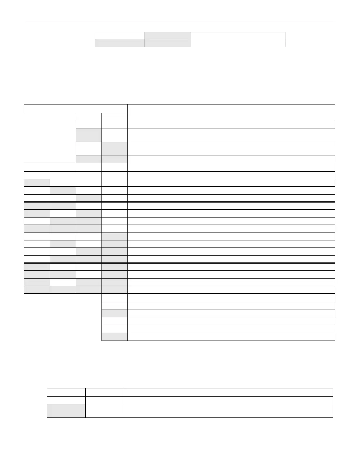
DIP Switch Position
Output Control Setting/Operation
12
OFF OFF NAC output will activate when Command Input #1 is activated.
ON OFF NAC output will activate when Command Input #2 is activated.
(Exception: this Input controls Horn silencing during Selective Silence operation.)
OFF
ON NAC output will activate when Command Input #3 is activated, if available. (If accidentally
programmed on a PSE-6, the system will default to Input #2.)
ON ON NAC output will activate when ANY Command Input is activated.
3 4 5 6 Output Control Setting/Operation
OFF OFF OFF OFF Unused/Unsupervised. Outputs will not activate. Factory default setting.
ON OFF OFF OFF Reserved- Outputs will not activate
OFF
ON OFF OFF Non-resettable auxiliary power
OFF OFF
ON OFF Resettable aux power
ON ON OFF OFF Door holder auxiliary power
ON OFF ON OFF Slave mode (NAC follower)
OFF
ON ON OFF Master mode - ANSI Temporal (Temporal 3)
ON ON ON OFF Master mode - CO Temporal (Temporal 4)
OFF OFF OFF
ON Master mode - Amseco/Potter
OFF
ON OFF ON Master mode - Gentex
OFF OFF
ON ON Master mode - System Sensor
OFF
ON ON ON Master mode - Wheelock
ON OFF OFF ON Master mode, Selective Silence - Amseco/Potter
ON ON OFF ON Master mode, Selective Silence - Gentex
ON OFF ON ON Master mode, Selective Silence - System Sensor
ON ON ON ON Master mode, Selective Silence - Wheelock
7 Output Control Setting/Operation (Only applies when ZNAC-PS is installed)
OFF Class B
ON Class A
8 Output Control Setting/Operation (Unused)
OFF Unused/Unassigned
ON Unused/Unassigned
Table 3.7 S2-S8 Output Circuit DIP Switch Settings
Position 1 Position 2 Output to Command Input Assignment
OFF OFF NAC will activate when Input #1 activates.
ON OFF NAC will activate when input #2 activates.
(Exception: this Input controls Horn silencing during Selective Silence operation.)
Table 3.8 NAC Activation Settings
 Loading...


