20 UDACT-2 — Instruction Manual P/N 54089:B3 10/29/2019
Installation and Wiring Relay Driver (Auxiliary Output) Connections - TB4
Important! The UDACT-2 must not be used to dial a phone number that is call-forwarded per requirements of UL 864 10th Edition.
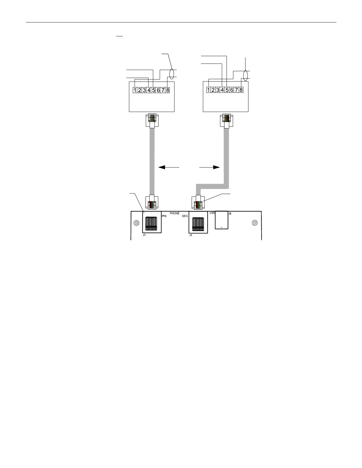
Figure 2.15 Wiring Phone Jacks
2.6 Relay Driver (Auxiliary Output) Connections - TB4
The UDACT-2's output on TB4 (RELAY DRIVE), is provided for Communicator Failure and UDACT-2 trouble. It can be used to drive
UL-listed relay MR-101/C or MR-201/C. The output is rated for 40 mA. The normal condition for the output is ON (energized).
Communicator Failure occurs when the maximum number of attempts to reach both Central Stations has taken place or when both phone
lines are disconnected. UDACT-2 trouble conditions include loss of telephone line voltage to the primary and/or secondary phone lines,
communication failure to the primary or secondary Central Stations, total communication failure, entry into program, type, and trouble-
shoot modes.
Wiring from the UDACT-2 terminal TB4 to the relay must be in the same room, no more than 20 feet in length, and enclosed in conduit.
Wiring from the relay output contacts must remain in the same room as the UDACT-2.
When the UDACT-2 is programmed for “Receive Only” (typically this occurs when annunciators are also used and are set for
“Receive/Transmit”), the relay output is used to provide a UDACT-2 trouble input to the host control panel. Use an FMM-1 module to
supervise the relay closure (refer to Figure 2.17 on page 21). Program the custom label field to read “UDACT-2 Trouble”.
Udact-2 jacks.wmf
RJ31X
Jack
RJ31X
Jack
Ring
Tip
Ring
Tip
Tip
Ring
Green
Green
Red
Red
To Premise Phones
To Premise Phones
Secondary Lines - Incoming Telco Phone Lines
Primary Lines-
Incoming Telco
Phone Lines
Shorting bars inside
jack removed during
male plug insertion
Secondary Phone
Line - PH-2
Primary Phone
Line - PH-1
Seven foot Cable
MCBL-7
(order separately)
Male Plug
Connectors
Modular Female
Connectors
Tip
Ring
 Loading...