UDACT-2 — Instruction Manual P/N 54089:B3 10/29/2019 13
Section 2: Installation and Wiring
2.1 Installation Options
The UDACT-2 is either installed internally in the panel cabinet or remotely in an ABS-8RB, UBS-1B or UBS-1R enclosure. The follow-
ing table contains information specific to each panel that is compatible with the UDACT-2. See "Internal Installation" on page 13 for
instructions on internal installation and "Remote Installation" on page 17 for instructions on remote installation. Additional information
required for installing the UDACT-2 in a specific Fire Alarm Control Panel will be found in the appropriate appendix relating to that
panel.
Table 2.1 Installation Options
Internal Installation
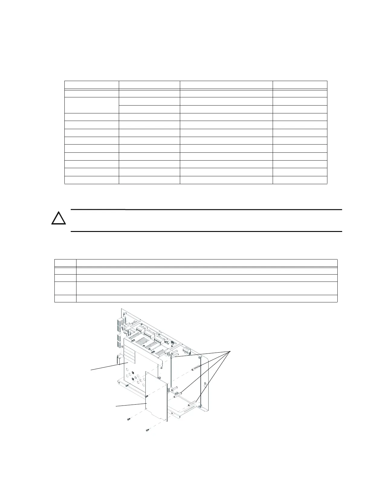
Mounting on the NFS-320 Chassis
The UDACT-2 is installed on the chassis within the NFS-320 backbox as described and shown below:
Host Control Panel Host Panel Cabinet Style Remote Cabinet Where Installed
AFP-200 AFP-200 Cabinet ABS-8RB, UBS-1B, UBS-1R Remote Only
AFP-300/AFP-400 CAB-400AA ABS-8RB, UBS-1B, UBS-1R Remote Only
CAB-3/4 Series ABS-8RB, UBS-1B, UBS-1R Internal or Remote
AM2020/AFP1010 CAB-3/4 Series ABS-8RB, UBS-1B, UBS-1R Internal or Remote
NCA-2 CAB-3/4 Series ABS-8RB, UBS-1B, UBS-1R Internal or Remote
NCA CAB-3/4 Series ABS-8RB, UBS-1B, UBS-1R Internal or Remote
NFS2-640 CAB-3/4 Series ABS-8RB, UBS-1, UBS-1B, UBS-1R Internal or Remote
NFS-320 NFS-320 Cabinet ABS-8RB, UBS-1, UBS-1B, UBS-1R Internal or Remote
NFS-320SYS CAB-3/4 Series ABS-8RB, UBS-1B, UBS-1R Internal or Remote
NFS-640 CAB-3/4 Series ABS-8RB, UBS-1B, UBS-1R Internal or Remote
NFS2-3030 CAB-3/4 Series ABS-8RB, UBS-1B, UBS-1R Internal or Remote
NFS-3030 CAB-3/4 Series ABS-8RB,UBS-1B, UBS-1R Internal or Remote
CAUTION:
REMOVE ALL POWER FROM THE CONTROL PANEL BY DISCONNECTING AC AND BATTERIES BEFORE
INSTALLATION OR MAKING ANY CONNECTIONS TO PREVENT PERSONAL AND/OR CIRCUIT DAMAGE.
Step Action
1 Disconnect AC power and disconnect batteries.
2 Remove the KDM-R2 keypad. Do not remove the onboard power supply.
3 Remove the two 1” standoffs from the bottom of the CPU and replace with the two #4-40 x 0.5” standoffs provided with
the UDACT-2.
4 Position the UDACT-2 on the standoffs and fasten with two #4-40 x 0.25” screws provided.
NFS-320
Chassis
screw and
standoff locations
UDACT-2-320chass.wmf
Onboard
Power Supply
UDACT-2
Figure 2.1 NFS-320 Chassis Installation
 Loading...