8 UDACT-2 — Instruction Manual P/N 54089:B3 10/29/2019
Overview Description
1.4 Description
The Universal Digital Alarm Communicator/Transmitter (UDACT-2) may be used with a variety of control panels. The UDACT-2 trans-
mits system status to UL Listed Central Station Receivers, using modular jacks to interface primary and secondary phone lines to the
public switched telephone network. The UDACT-2, which is compact in size, mounts internally in some panels or externally in a sepa-
rate enclosure. EIA-485 annunciator communications bus and 24 volt (nominal) connections are required. Install HWF2A-COM or
HWF2V-COM IP Digital communicators alongside the UDACT-2 to provide a secondary transmission path in lieu of a second phone
line, per UL 864 10th edition requirements (41.3.2.9). The UDACT-2 is compatible with the following panels and network annunciators:
For current and compatible firmware, log onto www.notifier.com and visit the Resources tab.
1.5 Features
• Dual telephone lines.
• Dual telephone line voltage detection.
• Digital Communicator provides:
• Line Seizure - takes control of the phone lines disconnecting any premises phones
• Dial tone recognition - 440 hertz tone typical in most networks
• Central Station number(s) dialing, Touch-Tone
®
• Protocols: SIA, 4 + 2, Ademco Contact ID.
• Programming created with VeriFire Tools, downloaded to UDACT-2 through USB port.
• Manual test report function.
• Manual master transmission clear function.
• Compact in size: 6.75" x 4.25".
• Mounts in the panel box or in a separate enclosure.
• Communicates vital system status including:
– Independent zone/point alarm, trouble and supervisory
– Security, panel off-normal, NAC trouble
– AC (main) power loss (programmable report delay).
• LED status indicators for power, EIA-485 loss, primary and secondary line seizure, line failure, lack of tone, kissoff,
communication failure, and manual test. (Refer to Table 1.3 on page 11 for a complete list.)
• Relay driver for Total Communication Failure or UDACT-2 trouble.
• Real Time Clock keeps time for up to 48 hours when the UDACT-2 is unpowered. (UDACT-2 must be powered for 24 hours or
longer to ensure the 48 hours. Handling or moving the unit may discharge it faster.)
• Simple EIA-485 interface to host panel.
• Up to 14 point trouble messages transmitted per hour.
1.6 Specifications
1.6.1 DC Power - TB1
Requires 24VDC (nominal) regulated, non-resettable and power-limited power. Supervised.
52 mA in standby, 72 mA maximum while communicating and 87 mA with the output engaged and communicating.
12-18 AWG - wire must be sized for a voltage drop of no more than two volts.
• NFS2-3030 • NFS-3030
• NFS2-640 • NFS-640
• NFS-320 • AFP-200
• NCA-2 • NCA
• AM2020/AFP-1010 • NFS-320SYS
• AFP-300/400
NOTE: Only one UDACT-2 can be installed on a host’s EIA-485 ACS circuit.
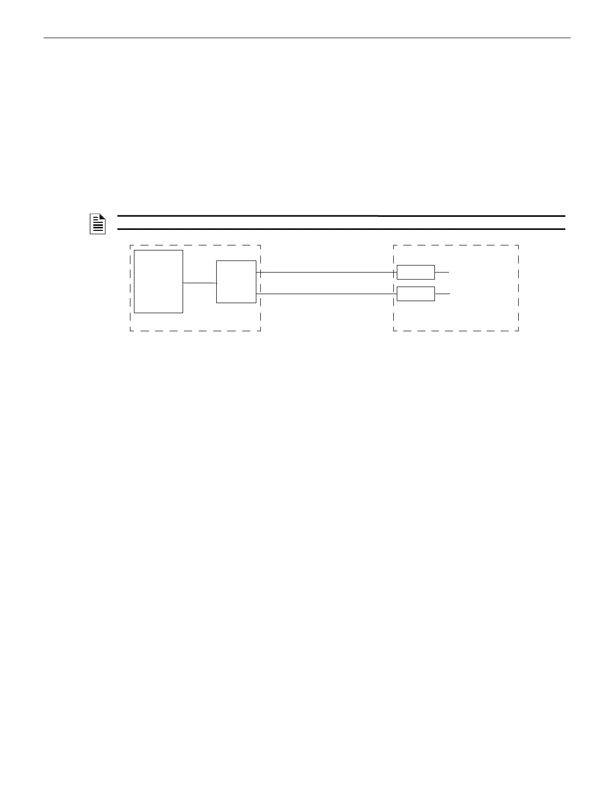
Figure 1.1 Block Diagram of a UDACT-2 Setup
Printer or monitor
Printer or monitor
Receiver
Receiver
Panel or
Network
Annunciator
UDACT-2
EIA-485
Public Switched
Telephone Network Lines
Protected Premises
Central Station(s)
 Loading...