18 Honeywell Sensing and Control
Signal Conditioning, Self Calibrating Digital Indicators
Rev. G, 008-0608-00
5.3 Function Input Pins
5.3.1 Overview
To use a Function Input pin (9, 10, 11 or 21), connect it to the
DGND (pin 19) momentarily. This can be accomplished by a
push button switch, relay contact closure, or PLC output.
Usually, the Function Input pins perform the default actions de-
scribed in the “System Connector Pinout” on page 17. However,
a SensoCode program running on a Mathematics Virtual Channel
may replace these default actions. Consult the Customer Infor-
mation Sheet included with your instrument for details.
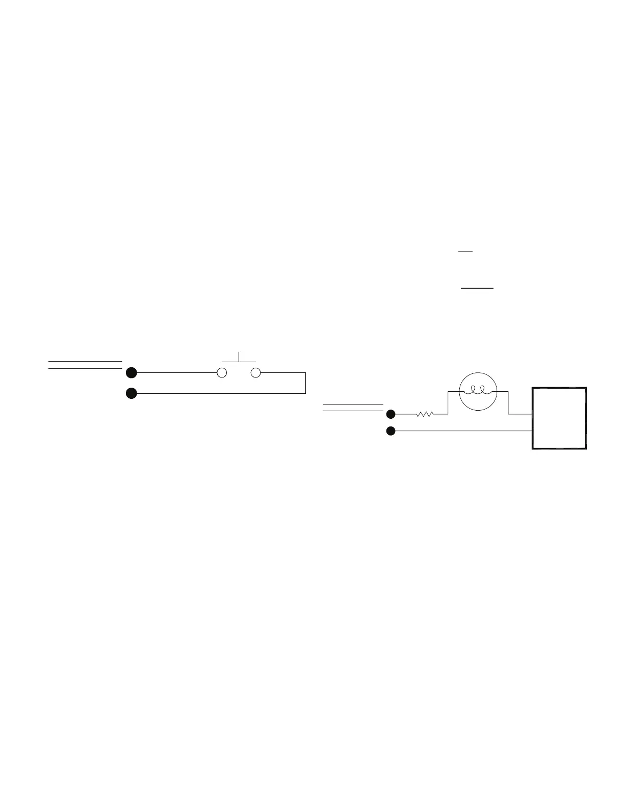
5.3.2. Example
For example, assume that you wish to use Function Input #3 to
tare all channels in the instrument simultaneously. Connect a
push-button switch as shown below.
Figure 5-1: Function Input Example
SWITCH
DIGITAL GROUND
19
DESIGNATION
FUNCTION INPUT 3
PIN
21
SYSTEM CONNECTOR
5.4 Limit Output Pins
5.4.1 Overview
An open-collector output is a transistor logic output that can be
used to control dc loads, drive opto-isolators or relays, or inter-
face directly to logic circuitry. They act very much like switches:
low resistance when turned on and high resistance when turned
off. You can use them as you would a dry relay contact, with the
following restrictions:
• Thevoltageappliedmustbedc
• Thepolarityofthedcvoltagemustbeobserved
• Maximumvoltage:50Vdc
• Maximumpower:2.0W
When Limits 1, 2, 3, or 4 are activated, the corresponding open-
collector Limit Output pin on the System connector will be con-
nected to the DGND (Digital Ground) pin. However, a SensoCode
program running on a Mathematics Virtual Channel may override
this behavior. Consult the Customer Information Sheet included
with your instrument for details.
5.4.2 Example
For example, assume that a remote indicator is to be lighted
when Limit 1 is activated. An external 24 Vdc power supply con-
nects to the indicator.
When Limit 1 is deactivated, there is high resistance between
the Limit 1 Output pin and the DGND (Digital Ground) pin; little
current flows in the circuit and the light is off. When Limit 1 is
activated, there is low resistance between the Limit 1 Output pin
and the DGND (Digital Ground) pin; the light turns on.
The resistor limits the current flowing in the circuit when the light
is lighted to 48 mA. According to Ohm’s Law:
I =
R
48 mA =
24 V
500 Ω
Lights or other indicators have voltage, current, and/or power rat-
ings that must be observed in order to avoid damaging them.
Figure 5-2: Open-Collector Output Example
(+)
24 Vdc
POWER SUPPLY
(-)
INDICATOR LIGHT
500 OHM
RESISTOR
DIGITAL GROUND
19
DESIGNATION
LIMIT 1 OUTPUT
PIN
14
SYSTEM CONNECTOR

 Loading...