Honeywell Sensing and Control 27
SC 2000, SC2001, SC3004
Rev. G, 008-0608-00
10.2 Wiring
Connect the transducer to a Strain-Gage Input channel by wiring
it to the 12-pin connector of that channel. The Customer Infor-
mation Sheet that shipped with the instrument describes which
cards are installed in each channel. The pin-out for this connector
is shown on the following table.
Table 10-1: Strain Gage Input Channel Pin Connectors
Pin Label Function Ref.
Pin
1 (top) +EXC (+)Excitation 10
2 +SEN (+)Sense 10
3 -SEN (-)Sense 10
4 -EXC (-)Excitation 10
5 +SIG (+)Signal 10
6 -SIG (-)Signal 10
7 +OUT Analog Output 8
8 -OUT Analog Return -
9 +MEM (+)Signature 10
10 -MEM (-)Signature / Digital Ground -
11 AUX1 Auxiliary Function 1 (connect to
pin 10 to activate)
10
12
(bottom)
AUX2 Auxiliary Function 2 (connect to
pin 10 to activate)
10
The Analog Output and Analog Return pins are electrically iso-
lated from all other pins on the instrument.
The maximum recommended cable length to a Signature Module
is 100 feet [30m].
NOTICE
If you are not using remote sensing of excitation, jumper (+)
Sense to (+)Excitation and (-)Sense to (-)Excitation. If nothing
is connected to (+)Sense and (-)Sense, the instrument will
enter the ERROR mode with error code 46.
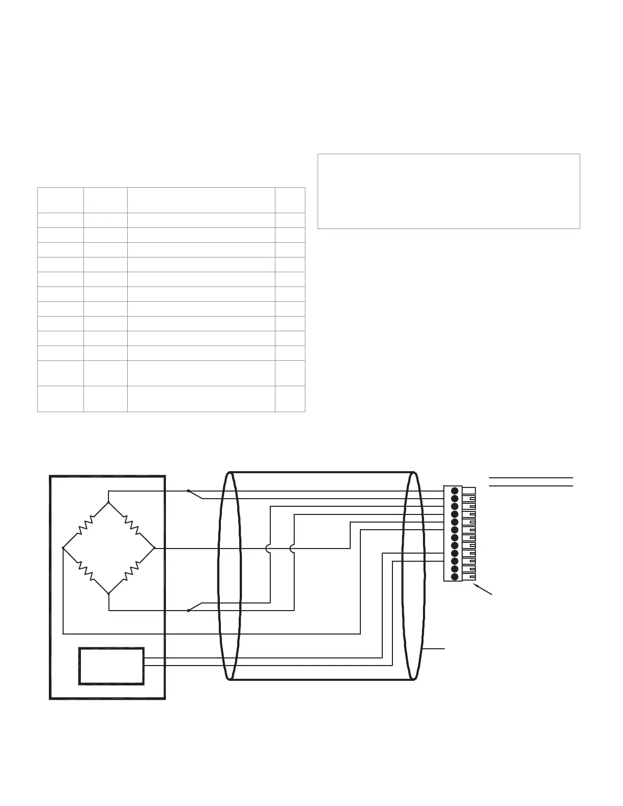
Figure 10-1: Unamplied Transducer Connection to Strain-Gage Input Channel
1
2
3
4
5
6
7
8
9
10
11
12
(+)EXCITAT ION
(+)SENSE
(-)SENSE
(-)EXCITAT ION
(+)SIGNAL
(-)SIGNAL
(+)ANALOG OUTPUT
(-)ANALOG OUTPUT
(+)SIGNATURE
(-)SIGNATURE/DGND
AUX1
AUX2
DESIGNATION
PIN
CABLE SHIELD CONNECTION SCREW
(+)EXCITATION
(-)EXCITATION
(+)OUTPUT
(-)OUTPUT
TRANSDUCER CABLE INSTRUMENT CONNECTIONS
(CONNECT TO CABLE SHIELD)
SIGNATURE
MODULE
(+)SIGNAT URE
(-)SIGNATURE
NOTE KEYED CONNECTOR
(OPTION 53e)

 Loading...