54 Honeywell Sensing and Control
Signal Conditioning, Self Calibrating Digital Indicators
Rev. G, 008-0608-00
12.2.7 “2-wire Current” Ampliers with Single-
wire Shunt Cal
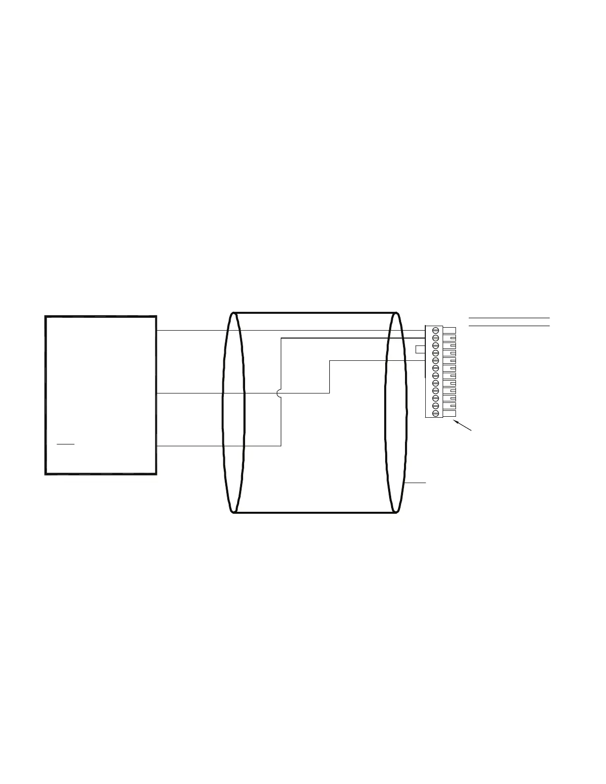
Use the following wiring diagram when connecting an amplified
transducer or in-line amplifier with a 2-wire current amplifier to a
High-Level Input channel. Examples of such devices include
• transducerswiththeOption2pinternalamplier(not
equipped with shunt cal)
• transducerswiththeOption2p,3dinternalamplier(single-
wire shunt cal)
• transducerswiththeOption2yinternalamplier(not
equipped with shunt cal)
• transducerswiththeOption2y,3dinternalamplier(single-
wire shunt cal)
The High-Level Input channel’s Configuration Jumpers must be
set as follows for proper operation. See “Excitation and Signal
Jumpers” on page 56.
• (+)Excitationsupply:“+28Vdc”
• (-)Excitationsupply:“GND”
• Signaltype:“current”
• Signalreference:“singleended”
Figure 12-6: “2-wire Current Amp w/Single-Wire Shunt Cal” Connection to High-Level Input Channel
1
2
3
4
5
6
7
8
9
10
11
12
(+)EXCITAT ION
SHUNT CAL 1
SHUNT CAL 2
(-)EXCITAT ION
(+)SIGNAL
(-)SIGNAL
(+)ANALOG OUTPUT
(-)ANALOG OUTPUT
N/C
DGND
AUX1
AUX2
DESIGNATION
PIN
CABLE SHIELD CONNECTION SCREW
(+)SUPPLY
SHUNT CAL 1
(+)OUTPUT
IN-LINE AMPLIFIER
CABLEINSTRUMENT CONNECTIONS
(CONNECT TO CABLE SHIELD)
OR
NOTE: SHUNT CALIBRATION
NOT AVAILABLE ON ALL
DEVICES.
LOOP POWERED,
CURRENT OUTPUT,
DEVICE WITH
NOTE KEYED CONNECTOR
+28V
SINGLE-WIRE
SHUNT CAL
0V

 Loading...