56 Honeywell Sensing and Control
Signal Conditioning, Self Calibrating Digital Indicators
Rev. G, 008-0608-00
12.3 Excitation and Signal Jumpers
12.3.1 Overview
The High-Level Input channel has hardware jumpers which al-
lows configuration of excitation supply voltages and signal inputs
to match the wide variety of amplified pressure, load and dc-dc
LVDT transducers.
CAUTION
“Wiring” on page 48 explains which jumpers settings are
required for a particular transducer type. Incorrect placement
of the Excitation and Signal jumpers can damage both the
transducer and the instrument.
Failure to comply with these instructions may result in
product damage.
12.3.2 Setting Jumpers
• Step1:Findthe“CaseRemoval”sectioninChapter4“Chas-
sis Models” on page 9 that matches the particular chassis
model. Follow the directions and remove the rear panel.
• Step2:Removethechannelboardfromthechassis.
• Step3:Changethejumpersettingsaccordingtothegure
below.
• Step4:Re-installthechannelboardandreplacetherear
panel.
CAUTION
There are two separate jumpers for the “signal type” whose
settings must match.
Failure to comply with these instructions may result in
product damage.
12.4 Calibration Procedure
If you are not familiar with operating the instrument in the SETUP
menu mode, see “SETUP Menu mode” on page 7. A listing of all
menu items is given in “Setup Menu Reference” on page 77.
• Step1:Wirethetransducertothechannel’sconnector.
See “Wiring” on page 48 for details.
• Step2:SettheExcitationandSignaljumpersappropriatefor
the transducer, amplifier or dc-dc LVDT.
See “Wiring” on page 48 and “Excitation and Signal Jump-
ers” on page 56.
• Step3:EntertheCALIBRATION TYPE.
There are two methods that can be used to calibrate the
transducer to the Input Channel. Each has advantages and
disadvantages as described in “CALIBRATION TYPE Menu
Item” on page 59. It is important to know your application in
order to select the appropriate calibration type.
• Step4:EntertheCALIBRATION DATA.
Otherwise, consult the Certificate of Calibration for the trans-
ducer when entering information in the CALIBRATION DATA
sub-menu.
• Step5:Performthecalibration.
Using the CALIBRATE menu item starts the calibration pro-
cess. You will be prompted to apply loads to the transducer
as required.
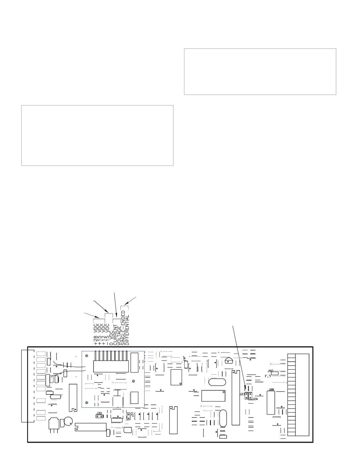
Figure 12-8: Excitation and Signal Jumper Locations on the
High-Level Input Channel
(+)EXCITATION
SUPPLY
(-)EXCITATION
SUPPLY
SIGNAL REFERENCE
SIGNAL TYPE (2 of 2)
CURRENT = J23 INSTALLED
VOLTAGE = J23 REMOVED

 Loading...