Honeywell Sensing and Control 37
SC 2000, SC2001, SC3004
Rev. G, 008-0608-00
10.7 Troubleshooting
10.7.1 Error Messages
See “Error Messages” on page 73 for information relating to error
messages.
10.7.2 Common Problems and Solutions
Erratic Display
• Checkelectricalconnectionsforcontinuityandthetrans-
ducer’s wiring code from its Certificate of Calibration.
• Makesurethattheloadonthetransducerisconstant.
• Checkmillivoltinputtothe(+)Signal(“+SIG”)and(-)Signal
(“-SIG”) pins with a voltmeter.
+OVLD or -OVLD on Display
Indicates that the voltage across the (+)Signal (“+SIG”) and (-)
Signal (“-SIG”) pins is overranging or underranging the amplifier
circuit. Make certain all wires are connected properly.
If you remove all load from the transducer and you still see this
message, the (+)Excitation (“+EXC”) or (-)Excitation (“-EXC”) pins
may be shorted to the (+)Signal (“+SIG”) or (-)Signal (“-SIG”)
pins.
If you remove all load from the transducer and you get a numeric
reading, the transducer may have a high zero offset. Use the
channel’s SETUP menu and set DIAGNOSTICS -> DISPLAY ADC to
“ON”; in the RUN mode this will allow the [VALUE] button to dis-
play raw A/D readings as a percentage of its full-scale. If the raw
A/D readings display more than +/-10% when there is no load on
the transducer, the transducer has a high zero offset.
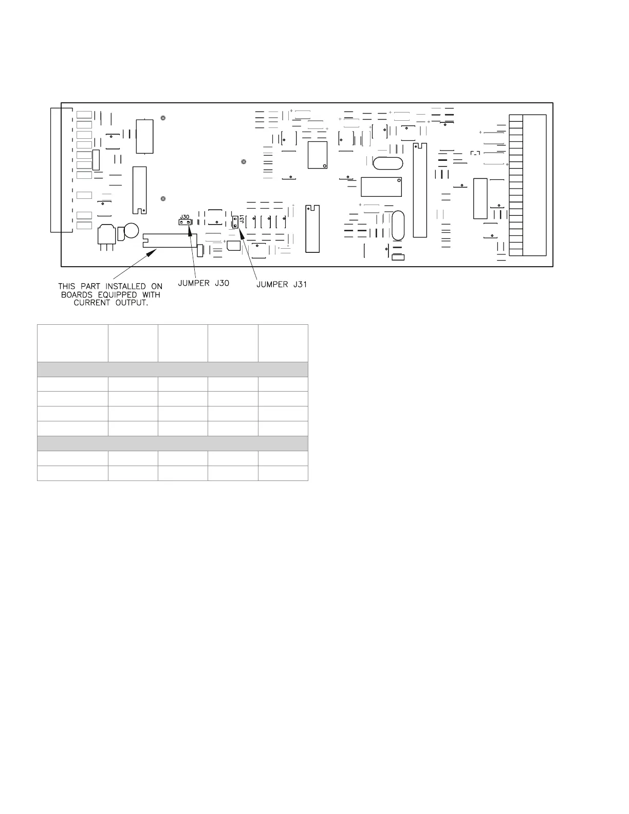
Figure 10-3: Digital-to-Analog Output Jumper Locations
DAC. ZERO
SCALE
Output
DAC. FULL
SCALE
Output
J30
jumper
J31
jumper
CHANNELS WITH VOLTAGE OUTPUT
0 V to 5 V 2.5 Volts 5 Volts open closed
±5V 0 Volts 5 Volts open open
0 V to10 V 5 Volts 10 Volts closed closed
±10V 0 Volts 10 Volts closed open
CHANNELS WITH CURRENT OUTPUT
4 mA to 20 mA 4 mA 20 mA open open
4 mA to 20 mA 12 mA 20 mA open closed

 Loading...