46 Honeywell Sensing and Control
Signal Conditioning, Self Calibrating Digital Indicators
Rev. G, 008-0608-00
11.7 Analog Output Conguration
11.7.1 Identifying the Output Type
An AC/AC-LVDT Input channel is available with one of two types
of digital-to-analog (DAC) outputs: voltage or current. You can
determine which type of output a channel has by one of three
ways:
• Consultingtheinstrument’sCustomerInformationSheet
• ExaminingtheSYSTEM MENU -> CONFIGURATION -> CHANNEL nn
TYPE menu item where nn is the number of the channel. If the
channel’s type is AC-AC LVDT V, it has a voltage output. If the
channel’s type is AC-AC LVDT I, it has a current output.
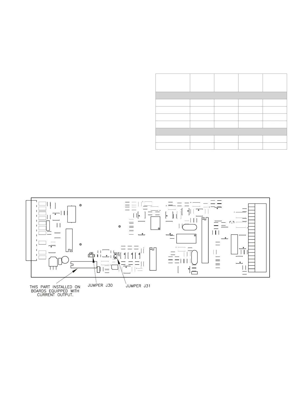
• Examiningthechannel’scircuitboardasshowninthegure
below.
11.7.2 Channel Menu Items
The Analog Output can be driven by any channel’s track, peak or
valley value.
See the “Channel Menu” section earlier in this chapter for a com-
plete listing of SETUP menu items available on the DAC. SETUP
sub-menu.
11.7.3 Output Selection
Jumpers located on the channel’s circuit board determine what
outputs are generated when the value selected to drive the Ana-
log Output (from the DAC. CHANNEL and DAC. SOURCE menu items)
equals the DAC. FULL SCALE and DAC. ZERO SCALE settings.
Figure 11-2: Digital-to-Analog Output Jumper Locations
DAC. ZERO
SCALE
Output
DAC. FULL
SCALE
Output
J30
jumper
J31
jumper
CHANNELS WITH VOLTAGE OUTPUT
0 V to 5 V 2.5 Volts 5 Volts open closed
±5V 0 Volts 5 Volts open open
0 V to10 V 5 Volts 10 Volts closed closed
±10V 0 Volts 10 Volts closed open
CHANNELS WITH CURRENT OUTPUT
4 mA to 20 mA 4 mA 20 mA open open
4 mA to 20 mA 12 mA 20 mA open closed