System 57 Quick Start Guide 05701-M-5026 MAN0839 Issue 1
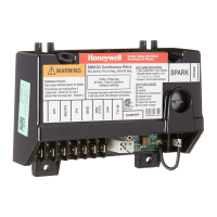
8.3.1 4-20mA loop powered detector (measuring resistor in supply
return)
01
-
+
28
27
Detector
S
5701 Interface Card
Sensor Drive Module
Link Positions 13, 10
& 4.
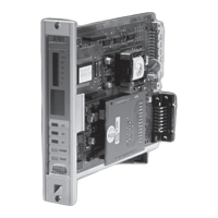
8.3.2 4-20mA loop powered detector (measuring resistor in supply
positive line)
NS
01
-
+
29
28
Detector
5701 Interface Card
Sensor Drive
Module Link
Positions 9, 6 & 1.
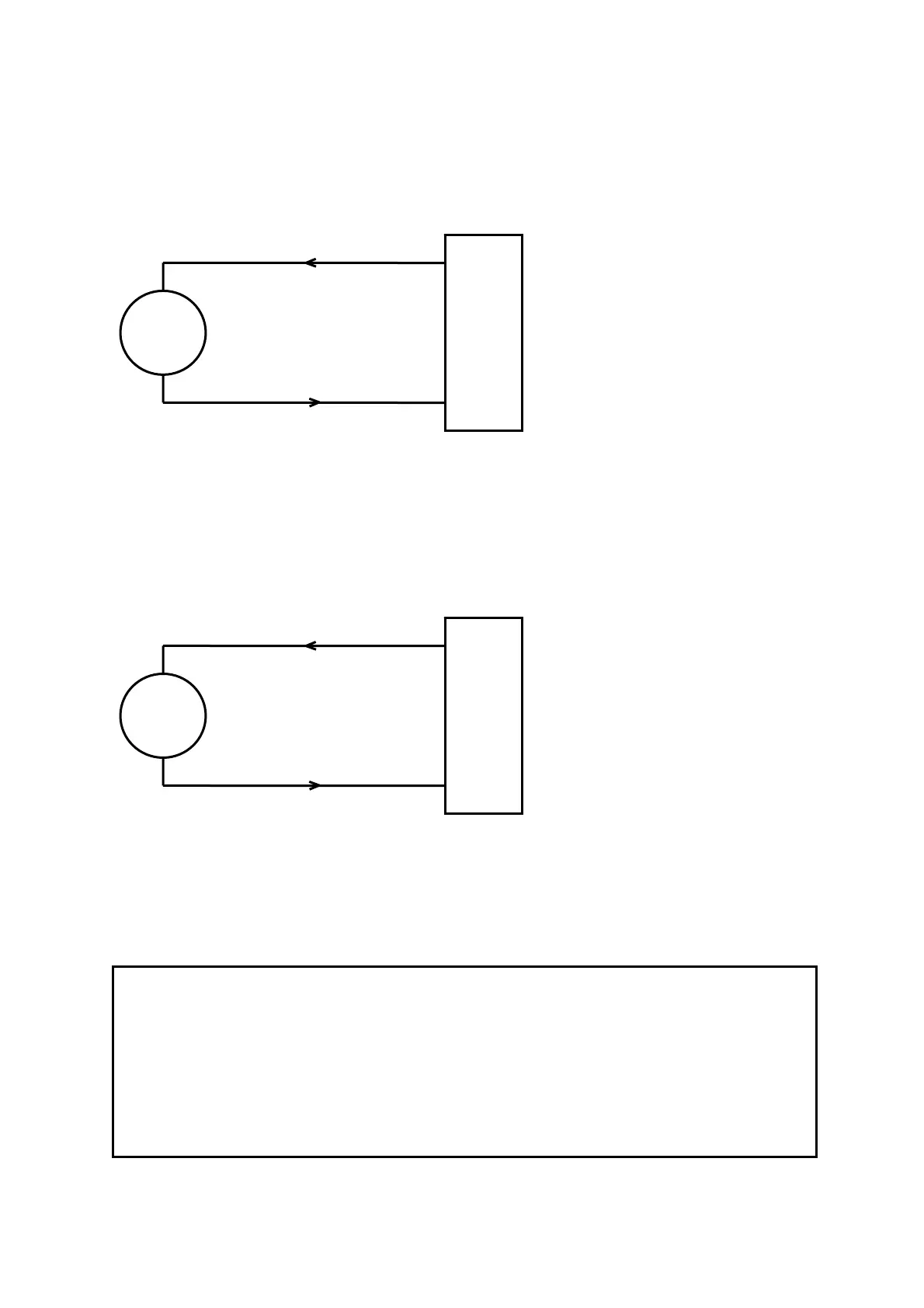
8.4 5701 Gas Card and 3 Wire 4-20mA Transmitter
CAUTION
The power provided by the Single Channel Control Card is derived from the dc
input to the System 57 (18V to 32V). Check that the transmitter to be connected is
compatible with the actual supply voltage used.
The maximum current that may be sourced from the field terminals of an individual
Single Channel Control Card to power a field device is 500mA, however, the total
current sourced from all the channels should not exceed the maximum backplane
load current of 8A.
10
 Loading...