System 57 Quick Start Guide 05701-M-5026 MAN0839 Issue 1
Where the cable consists of a separate screen sheath and wire armour or braid, the armour
should be co
nnected at the cabinet entry to the protective earth and the screen sheath
sistor, shown with
typical value of 620 ohms, if not this can be easily fitted externally within the call point
5W, to set the alarm current.
to
his will not suppress the alarm output but a fault
ble should be connected at one end only to
.8.6 Detectors with Voltage Free Contact Outputs
e alarm
t. These types of detector
to connect
inals of the Hex Relay Interface Card that is attached
line (EOL) resistor must be fitted in or after the last
ted
cabinet by
nnected at the cabinet entry to the protective earth and the screen sheath
should be connected to the GROUND terminal of the Hex Relay Interface Card or to a
suitable instrument earth point.
Notes: 1. Most modern call points already incorporate the alarm current re
a
junction box.
2. The Fire Card inputs are also compatible with devices that use a zener diode, typical
value 8.2V, 0.
3. The operation of more than two call points simultaneously may cause the loop current
exceed the short circuit warning threshold. T
indication will be given on the fire card display.
4. Where the call point is earthed locally, either to an Earth Stud or through the sensor
casing or mounting, the screen sheath of the ca
avoid earth loops.
8
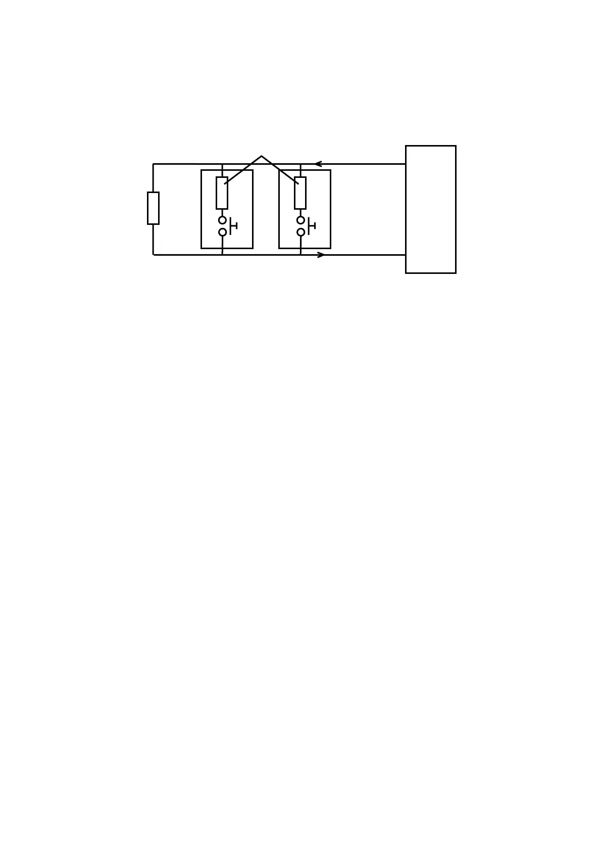
Some fire detectors (especially flame) are equipped with a voltage free contact for th
output and often with a second voltage free contact for fault outpu
are easily connected to the fire card using a two wire connection. The detector
documentation will indicate the voltage free contact connections. Although a number of
detectors may be connected in parallel on a single loop input, it is good practice
only one flame detector on any input.
At the System 57 end of the field cables the signal wires should be connected to the
appropriate channels IN+ and IN- term
to the required 5704F Control Card.
The loop current always flows from the IN+ terminal and returns via the IN- terminal. For
fault monitoring purposes, an end of
detector on the loop. The typical value for end of line resistance is 5.1k ohms.
The detector cable screen or steel wire armour or braid as appropriate, should be connec
to the system protective earth. This can be achieved where the cable enters the
using a metal cable gland, or by other suitable means, and avoiding any screen tails within
the cabinet.
Where the cable consists of a separate screen sheath and wire armour or braid, the armour
should be co
620
620
EOL
5.1k
IN-
23
21
Alarm Current Resistor
IN+
Manual Call Points
5704 Hex Card
The diagram shows the detect annel 1. Channel 2, 3 and 4 connec
rminal connection numbers are shown in section 7.
or connections for Ch tions
are similar and their te
18

 Loading...