System 57 Quick Start Guide 05701-M-5026 MAN0839 Issue 1
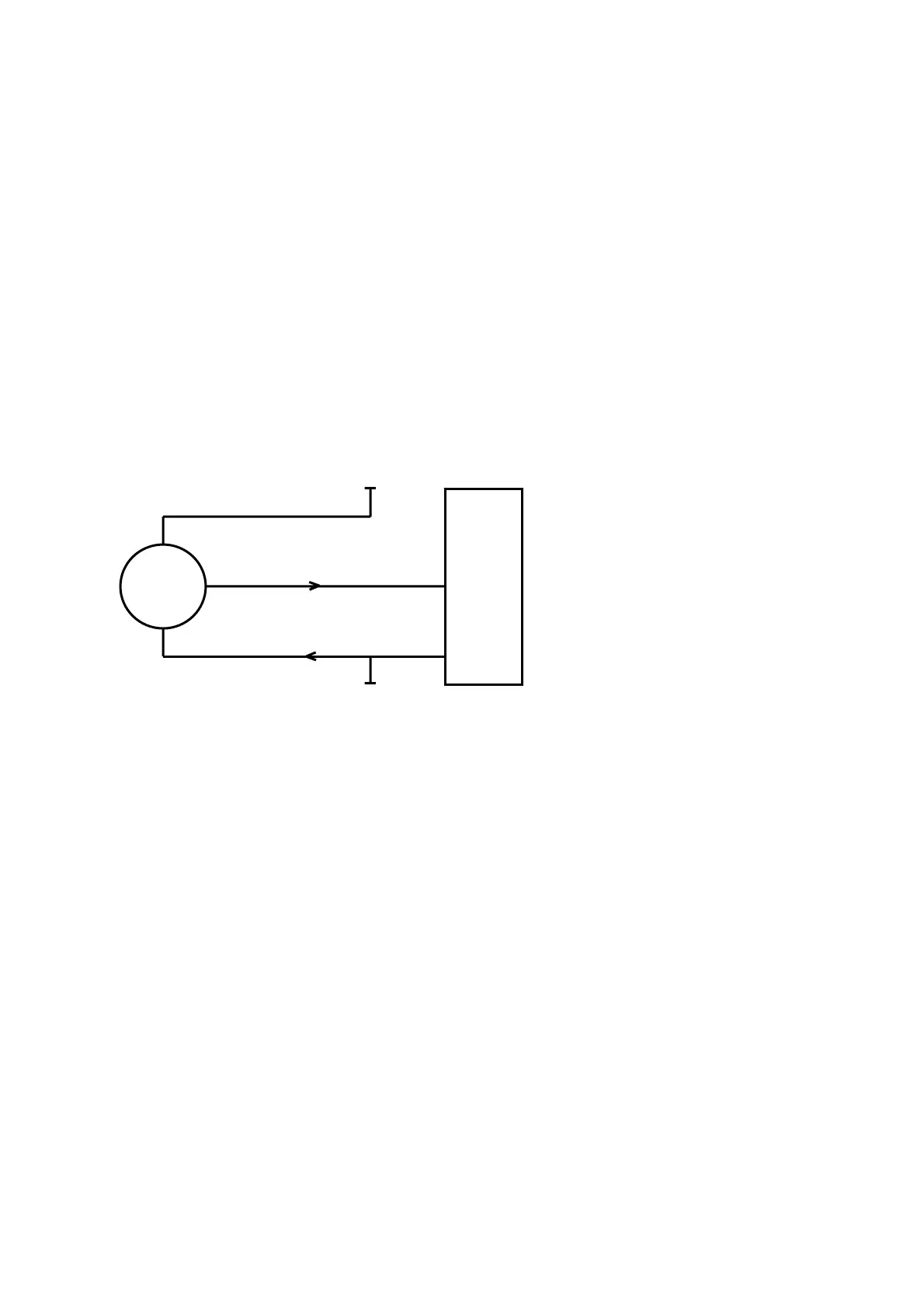
8.7 5704 Gas Card and 3 Wire 4-20mA Transmitter
ctor documentation
ould be
4V
ote: Terminals 35 and 36 on the Relay Interface Card are input terminals only and cannot
he Schematic below details the connections for 3 wire current source transmitters. For
.
Transmitters require either three or four wire connections and the dete
will indicate the 0V and +24V power connections and the positive and negative loop
connections. At the System 57 end of the field cable the detector loop signal wires sh
connected to the S, 01, NS terminals on the Quad Relay Interface Card that is attached to
the required Four Channel Control Card. The exact terminals used vary depending upon
whether three or four wire topology is used, the requirement for a loop current source
configuration and the channel to be connected to. The transmitter power connection +2
and 0V should be connected to a suitable dc supply.
N
be used to power the transmitter.
T
other schematics (including isolated and barrier) refer to operating manual 05704-M-5001
+24V
0V*
NS
01
4-20mA
19
17
Transmitter
0V
5704 Quad Card
The diagram shows the detector connections for Channel 1. Channel 2, 3 and 4 connections
+24V*
*24V supply may be obtained
from either the cabinet or a
separate field supply.
are similar and their terminal connection numbers are shown in section 7.
13
 Loading...