System 57 Quick Start Guide 05701-M-5026 MAN0839 Issue 1
The detector cable screen, or steel wire armour or braid as appropriate, should be
connected to the system protective earth. This can be achieved where the cabl
e enters the
screen
the cabinet entry to the protective earth and the screen sheath
otes: 1. Separate provision may be required for power supply isolation in order to reset the
etector after an alarm condition. Consult the detector operating instructions for more
th the system layout to minimise electrical noise and other forms of interference.
ne
.8.5 Call Points and Simple Switched Output Detectors
ed alarm
the switch contact
rd that is
t
r end of line resistance is 5.1k ohms.
o
binet by
cabinet by using a metal cable gland, or by other suitable means, and avoiding any
tails within the cabinet.
Where the cable consists of a separate screen sheath and wire armour or braid, the armour
should be connected at
should be connected to the GROUND terminal of the Hex Relay Interface Card or to a
suitable instrument earth point.
N
d
details.
2. For a 3 wire connection, the IN- signal can return via the 0V supply but care should be
taken wi
3. Where a detector is earthed locally, either to an Earth Stud or through the sensor casing
or mounting, to avoid earth loops the screen sheath of the cable should be connected at o
end only.
8
Manually Activated Call Points (MAC) and some fire detectors have a simple switch
output via two wire connection. The detector documentation will indicate
connections. Many call points may be connected in parallel on a single loop input, but it is
good practice to keep call points on a separate input to other types of detector.
At the System 57 end of the field cables the two call point signal wires should be connected
to the appropriate channels IN+ and IN- terminals of the Hex Relay Interface Ca
attached to the required 5704F Control Card. The loop current always flows from the IN+
terminal and returns via the IN- terminal.
For fault monitoring purposes an end of line (EOL) resistor must be fitted in or after the las
call point on the loop. The typical value fo
The detector cable screen, steel wire armour or braid as appropriate, should be connected t
the system protective earth. This can be achieved where the cable enters the ca
using a metal cable gland, or by other suitable means, and avoiding any screen tails within
the cabinet.
0V
24V
EOL
5.1k
UV/IR
Flame
0V
+24V*
36
+24V*
35
IN-
23
21
IN+
0V*
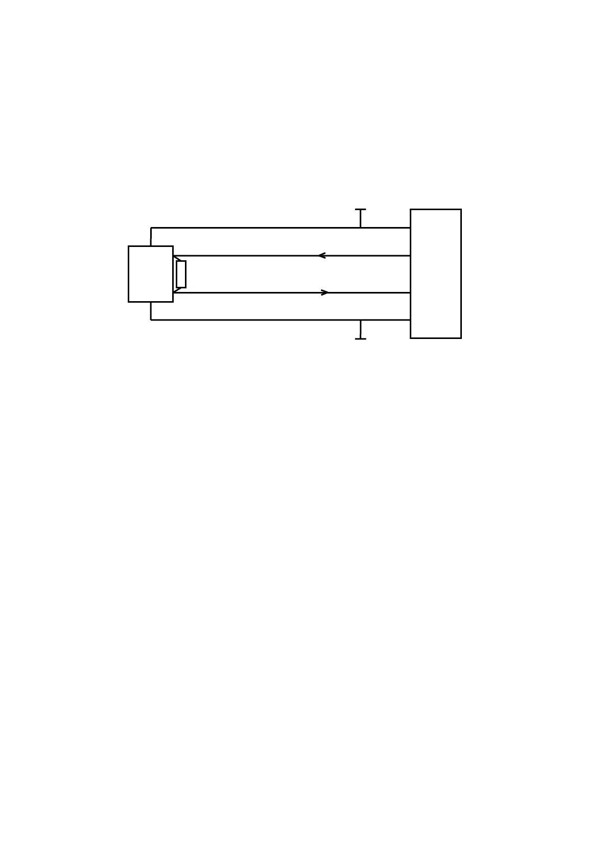
5704 Hex Card
Flame Detector
The di etector connections for Channel 1. Channel 2, 3 and 4 connect
rminal connection numbers are shown in section 7.
agram shows the d ions
are similar and their te
17

 Loading...