XNX Universal Transmitter
Installation and Operation
43
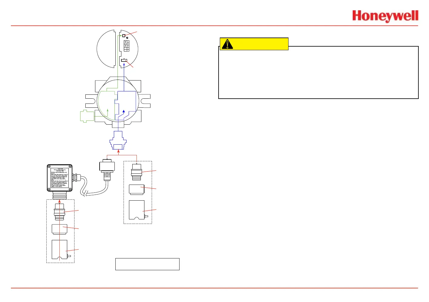
EC
Adaptor
IS Barrier must
be connected to J1
EC IS Barrier must
be connected to J2
4
3
2
1
-
+
6
5
J1 HART
S1 S2
J2 EC Barrier
Terminal Block 1
Local HART
IS Barrier
(optional)
HART
Adaptor
EC IS Barrier
Sensor Cartridge
Weatherproof Cap
Sensor Retainer
Sensor Cartridge
Weatherproof Cap
Sensor Retainer
Local Sensor Mounted to Transmitter
Sensor Mounted to
For FM compliance, the tag supplied with
XNXXSH1FM and XNXSO1FM cartridges must be
attached to the transmitter or remote mount kit.
Figure 40. EC personality wiring
Electrochemical Sensor Installation
Caution: A missing oxygen cell will result in 0% V/V O2 gas concentration, thus
triggering alarm events. In this situation, check the connection of the EC cell to the
sensor connector board.
Caution: For biased sensors (e.g., nitrogen dioxide) remove the sensor stabilizer from
the bottom of the sensor prior to installation.
!
Using the Installing plug-in sensor illustration as a guide, follow this
procedure:
1. Verify that the label on the new sensor is the correct gas
type.
2. Unscrew the weatherproof cover, loosen the retainer
locking screw with the supplied hex key, and unscrew the
sensor retainer.
3. Plug in the new sensor. Take care to align the sensor pins
with the connector.
4. Ret the sensor retainer, tighten the locking screw with the
hex key, and ret the weatherproof cover. Countdown time
of up to 180 seconds (depending on the sensor type) will
be displayed.
5. Acknowledge the gas type (required before proceeding).
For more information on setting gas type, see the Gas
Selection section.
6. After the sensor is installed and the gas type is conrmed,
the range, alarm levels, and other important settings must
be set; see the Conguring the Transmitter section.
7. After the transmitter has been congured, calibrate the
sensor following the procedures in the Calibration section.
 Loading...


