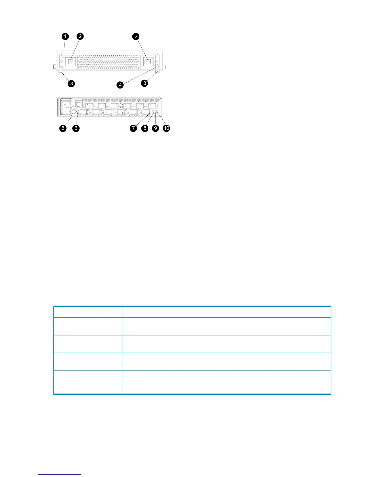
Figure 18 30-10010-02 loop switch status indicators
2. Bezel snaps1. Handle
4. Walk-up RS232 port3. Alignment tabs
6. Port Bypassed indicator5. SFP status indicator
8. Over Temp indicator7. POST fault indicator
10. Loop operational indicator9. Power indicator
Power-on self test (POST)
When you power on the 30-10010-02 loop switch, it performs a Power-on Self Test (POST) to
verify that the switch is functioning properly. During a POST, all of the indicators turn on for
approximately two seconds. Then, turn off all of the indicators, except the power indicator.
If the Port Bypass indicators are blinking at a constant rate and the POST Fault indicator is on, the
switch detected a fault during the POST. In this case, you need to contact your HP authorized
service representative.
Reading the switch status indicators
Figure 18 (page 46) shows the Fibre Channel switch with the system and port indicators.
Table 14 (page 46) lists and describes the system indicators.
Table 14 30-10010-02 loop switch status indicators
DescriptionSystem indicator
A green indicator. When lit, this indicates that the switch is plugged in and the internal
power is functional.
Power
A green indicator. When lit, this indicates that the Fibre Channel loop has completed
initialization and is now operational.
Loop operational
An amber indicator. When lit, this indicates that the internal hardware self-test failed
and the switch will not function.
POST fault
An amber indicator. When lit, this indicates that the ambient temperature has exceeded
40° C. The switch is still functional; however, you should correct the problem immediately.
The OverTemp indicator turns off when the problem is corrected.
OverTemp
Table 15 (page 47) describes the port indicators.
46 Enterprise Virtual Array hardware components
 Loading...