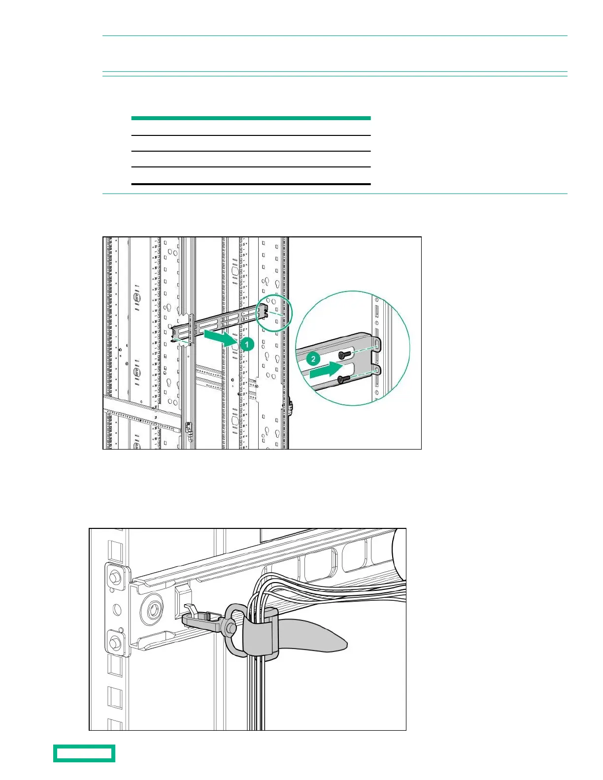
NOTE: The screw holes for the cross-over bracket are located on the side of the rear rack screw column, towards the inside
of the rack.
2. Using a T-25 Torx driver, insert two M55 x 10-mm Torx screws on each side of the cross-over bracket and secure to the
rack frame (2).
Installing the hook-and-loop cabling straps
Attach the clip to the rack in any of the following positions, then route and secure your cables with the hook-and-loop cabling
straps.
Cable Management Combo kit 25
NOTE: To avoid interference with the rear door lock, do not install in the following U range if the rear door will be closed.
Prohibited U heights
Rack
22U
07U~16U
36U
14U~23U
42U
16U~27U
48U
20U~29U

 Loading...