Valid Memory Configurations
The first cell must have one DIMM pair loaded in slots 0A/0B. The server can support as little
as 2 GB of main memory using two 1 GB DIMMs installed on one of the cell boards and as much
as 512 GB by filling all 16 DIMM slots on all four cell boards with 8 GB DIMMs.
The following rules explain the memory configuration:
1. DIMMs must be loaded in pairs (same size within a pair).
2. DIMM pairs must be loaded in slot order (0A/0B, 1A/1B, 2A/2B, ...)
3. Largest DIMMs must be loaded first followed by progressively smaller DIMM module sizes.
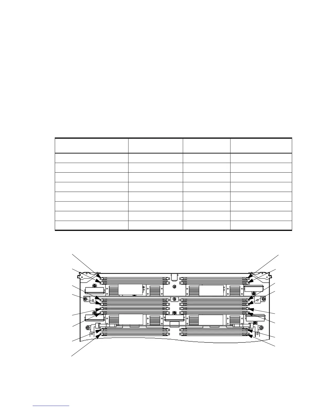
A paired set of DIMMs is called a rank. DIMMs in a rank must be of the same capacity. See
Table 1-3 and Figure 1-9for DIMM load order and layout on the cell board.
A quad is a grouping of four DIMMs (Figure 1-9). Configurations with 8 or 16 DIMM slots loaded
are recommended. Adding a rank enables a dedicated DDR-II bus on a cell to increase the amount
of usable memory bandwidth available. Available memory is proportional to the amount of
memory installed.
Table 1-3 DIMM Load Order
Quad LocationDIMM Location on Cell
Board
Action TakenNumber of DIMMs Installed
Quad 20A and 0BInstall first2 DIMMs = 1 rank
Quad 11A and 1BAdd second4 DIMMs = 2 rank
Quad 32A and 2BAdd third6 DIMMs = 3 rank
Quad 03A and 3BAdd fourth8 DIMMs = 4 rank
Quad 24A and 4BAdd fifth10 DIMMs = 5 rank
Quad 15A and 5BAdd sixth12 DIMMs = 6 rank
Quad 36A and 6BAdd seventh14 DIMMs = 7 rank
Quad 07A and 7BAdd last16 DIMMs = 8 rank
Figure 1-9 DIMM Slot Layout
 Loading...