Table 1-4 Removable Media Drive Path
PathRemovable Media
0/0/0/2/1.x
1
.0Slot 0 media
1/0/0/2/1.x
1
.0Slot 1 media
1 X equals 2 for a DVD drive while X equals 3 for a DDS-4 DAT drive.
Table 1-5 Hard Disk Drive Path
PathHard Drive
0/0/0/2/0.6.0Slot 0 drive
0/0/0/3/0.6.0Slot 1 drive
1/0/0/2/0.6.0Slot 2 drive
1/0/0/3/0.6.0Slot 3 drive
System Backplane
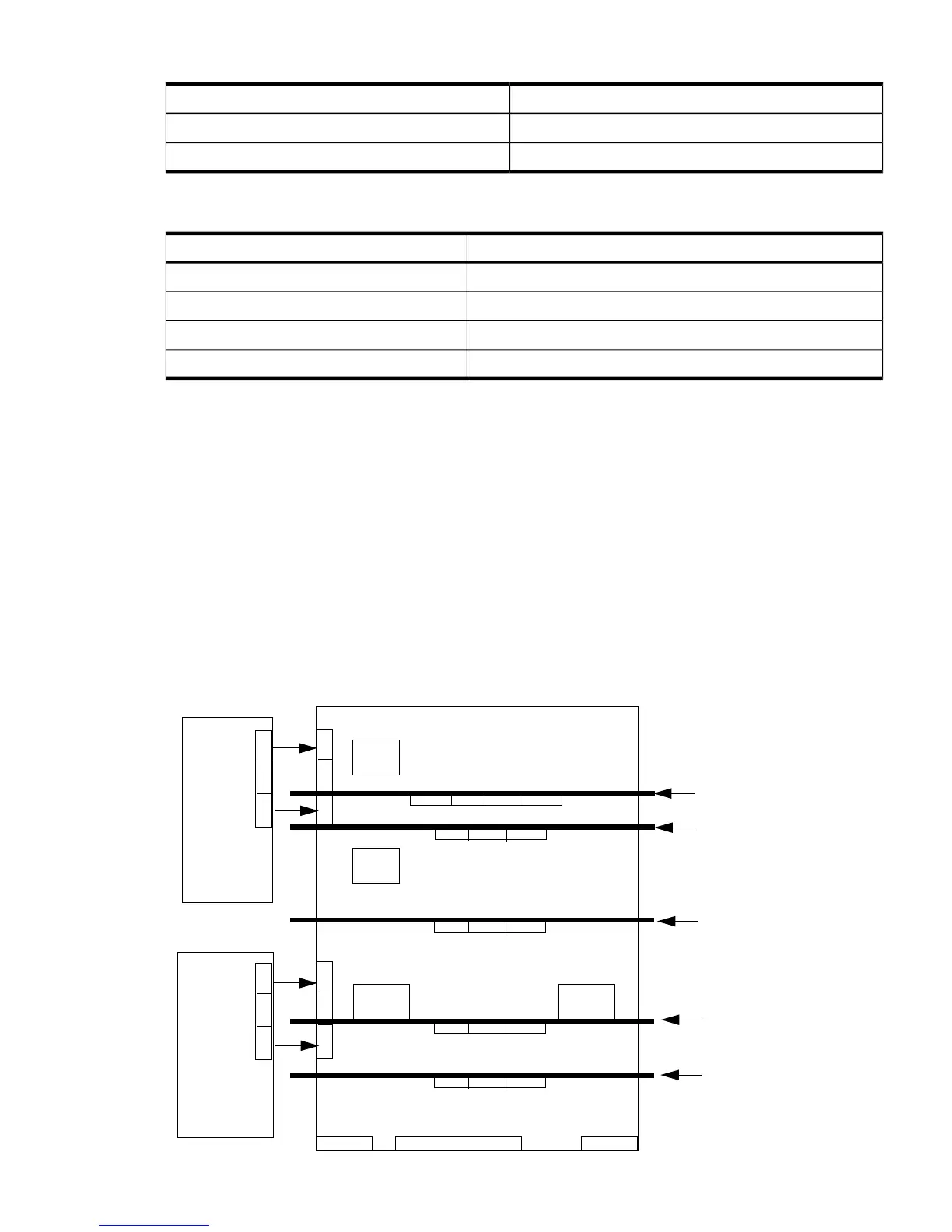
The system backplane board contains the following components:
• Two crossbar chips (XBC)
• Clock generation logic
• Preset generation logic
• Power regulators
• Two local bus adapter (LBA) chips that create internal PCI buses for communicating with
the core I/O card.
The backplane also contains connectors for attaching the cell boards, PCI-X backplane, MP core
I/O cards SCSI cables, bulk power, chassis fans, front panel display, intrusion switches, and
external system bus adapters (SBA) link connectors.
Figure 1-11 System Backplane Block Diagram
 Loading...