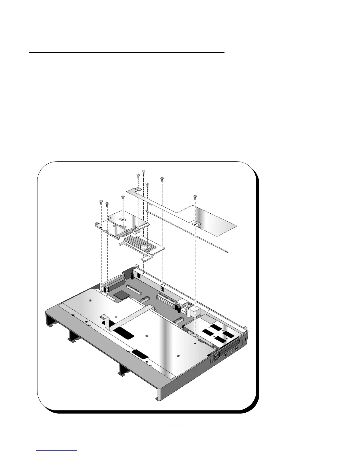
Removal of Motherboard (PCA PT-586 with I/O Bracket), HDD PCB Bracket, HDD-FPC Flex, FFC Cable
T/B to M/B 10 Pin, Bezel, IR Lens, and PCMCIA buttons.
The PCMCIA buttons can be removed at any stage of the disassembly process. They must, however, be removed before removing the
motherboard.
To remove the Motherboard (PCA PT-586 with I/O Bracket), HDD PCB Bracket, HDD-FPC Flex, FFC Cable T/B to M/B 10 Pin, Bezel, IR Lens,
first follow the instructions above to remove the HDD Drive, Center Bay Module (FDD Module, CD-ROM Assy, or Enhanced Li-Ion Battery),
Standard Li-Ion Battery, Palmrest Assy, Keyboard, PCA PT-DC, Upper Chassis Case, PCA PT-ICON Heat Pipe Bracket, Heat Pipe, Heat Pipe
Spreader, CPU Module, Heat Sink and KBD Shielding Plate.
The HDD PCB Bracket, the HDD-FPC Flex, and the FFC Cable T/B to M/B 10 Pin can all be removed without removing the PCA PT-586. When
removing the HDD-FPC Flex be sure to pull straight up on the connector, sideways pressure can damage or break the connector pins requiring
a full motherboard replacement..
To Remove the Motherboard (PCA PT-586 with I/O Bracket), remove the three screws (two are ISOT M2 X 6L and one is an ISOT M2 X 4L) that
hold the PCA PT-586
in place. Remove the
two standoffs (notice
that one is 11.75mm
long and the other is
15mm long). Remove
the Dock Grounding
Spring Plate. Remove
the two PCMCIA
buttons. Make sure
that you have removed
all RAM expansion
modules. Then lift the
PCA straight up. The
I/O Bracket comes as
part of the PCA
PT-586. If only the I/O
Bracket is damaged, it
can be ordered
separately and
replaced by removing
the 4 standoffs and
two screws from the
back of the bracket.
30
 Loading...