1. Prepare the computer for disassembly (see Preparation for disassembly on page 33).
2. Remove the bottom cover (see Bottom cover on page 33).
3. Disconnect the battery cable from the computer (see Battery on page 35).
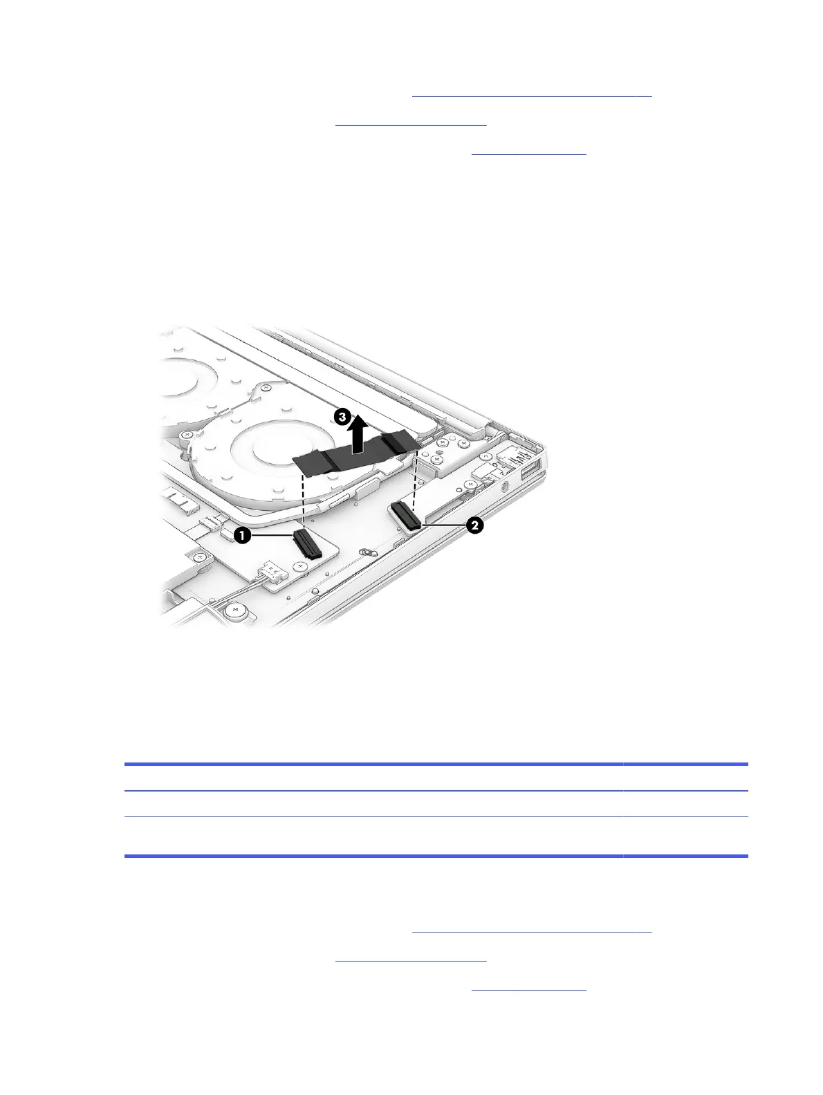
Remove the connector board cable:
1. Release the zero insertion force (ZIF) connector (1) the connector board cable is connected to, and
then disconnect the connector board cable from the system board.
2. Release the ZIF connector (2) the connector board cable is connected to, and then disconnect the
connector board cable from the connector board.
3. Remove the connector board cable (3) from the computer.
To replace the connector board cable, reverse the removal procedures.
Connector board
To remove the connector board, use this procedure and illustration.
Table 5-7
Connector board description and part number
Description Spare part number
Connector board (includes USB port and audio jack) N94773-001
NOTE: The connector board spare part kit does not include the connector cable. The connector
cable is available using spare part number N94774-001.
Before removing the connector board, follow these steps:
1. Prepare the computer for disassembly (see Preparation for disassembly on page 33).
2. Remove the bottom cover (see Bottom cover on page 33).
3. Disconnect the battery cable from the computer (see Battery on page 35).
42
Chapter 5 Removal and replacement procedures for authorized service provider parts
 Loading...