4. Remove the connector board cable (see Connector board cable on page 41).
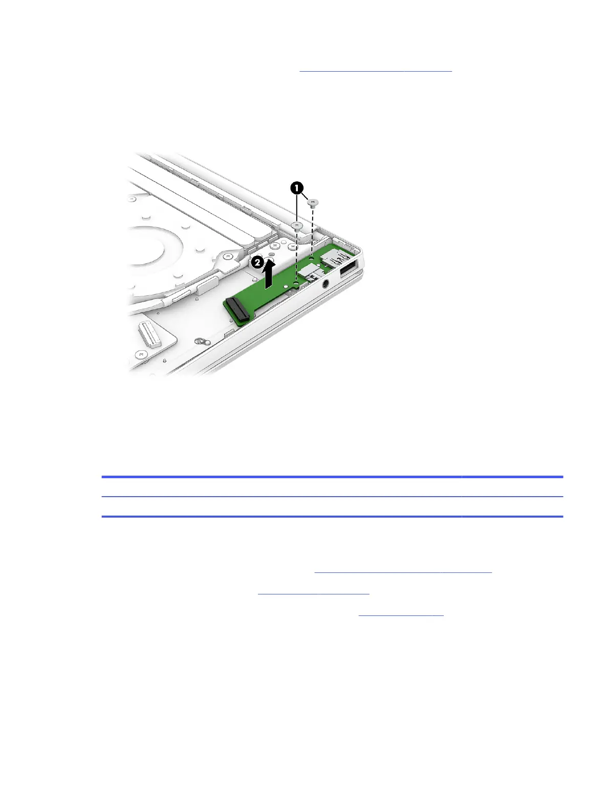
Remove the connector board:
1. Remove the two Phillips M2.0 × 2.9 screws (1) that secure the connector board to the computer.
2. Remove the connector board (2) from the computer.
To replace the connector board, reverse the removal procedures.
Fan
To remove the fan, use these procedures and illustrations.
Table 5-8
Fan description and part number
Description Spare part number
Fan (includes fan cable) N94801-001
Before removing the fan, follow these steps:
1. Prepare the computer for disassembly (see Preparation for disassembly on page 33).
2. Remove the bottom cover (see Bottom cover on page 33).
3. Disconnect the battery cable from the computer (see Battery on page 35).
Remove the fan:
1. Disconnect the fan cable (1) from the system board.
2. Release the display panel cable from the retention clips (2) that are built into the fan.
3. Remove the four Philllips M2.0 × 3.3 screws (3) that secure the fan to the computer.
Fan
43
 Loading...