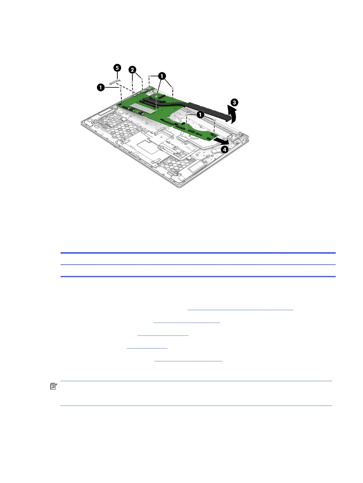
13. When removing the system board, be sure that the I/O bracket (5) is not misplaced. The I/O bracket
is is not available as a spare part.
To install the system board, reverse the removal procedures.
Heat sink
To remove the heat sink, use these procedures and illustrations.
Table 5-12
Heat sink description and part number
Description Spare part number
Heat sink (includes replacement thermal material) N94798-001
Before removing the heat sink, follow these steps:
1. Prepare the computer for disassembly (see Preparation for disassembly on page 33).
2. Remove the bottom cover (see Bottom cover on page 33).
3. Remove the battery (see Battery on page 35).
4. Remove the fan (see Fan on page 43).
5. Remove the system board (see System board on page 54).
Remove the heat sink:
NOTE: Steps 1 through 3 apply to computer models equipped with a graphics subsystem with
discrete memory. See steps 4 through 6 for heat sink removal information for computer models
equipped with a graphics subsystem with UMA memory.
1. In the order indicated on the heat sink, remove the four Phillips M2.0 × 3.3 screws (1) that secure the
heat sink to the system board.
Heat sink
57
 Loading...