2-5
Installing the Switch
Installation Procedure
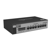
•The port Link LEDs turn on in sequence from port 1 to port 8, and then
the Mode LEDs flash once in sequence. Finally, the Link LEDs turn off
in the same sequence and the self test is complete.
When the self test completes successfully:
•The Power LED remains on.
•The Fault and Locator LEDs stay off.
• In the default state, the Act LED stays on and the Spd and FDx LEDs
stay off. The PD LED remains on when PoE power is available on
Port 1.
• The port LEDs on the front of the switch go into their normal opera-
tional mode:
– If the ports are connected to active network devices, the Link
LEDs stay on and the Mode LEDs behave according to the mode
selected. In the default mode (Act), the Mode LEDs should be
blinking indicating port activity.
– If the ports are not connected to active network devices, the Link
and Mode LEDs will stay off.
If the LED display is different than what is described above the self test
has not completed correctly. Refer to “Troubleshooting” for diagnostic
help.
3. Remove power to the switch before mounting.
3. Mount the Switch
The switch can be mounted in these ways:
■ on a horizontal surface
■ on a wall
■ under a table
Horizontal Surface Mounting
Place the switch on a table or other horizontal surface. The switch comes with
rubber feet that can be used to help keep the switch from sliding on the
surface.
Attach the rubber feet to the four corners on the bottom of the switch within
the embossed angled lines. Use a sturdy surface in an uncluttered area. You
may want to secure the networking cables and switch power cord to the table
leg or other part of the surface structure to help prevent tripping over the
cords.
 Loading...
