2-9
Installing the Switch
Installation Procedure
4. Connect the Switch to a Power Source
1. As before, power on the switch using the external power adapter module
or a PoE PD connection to Port 1.
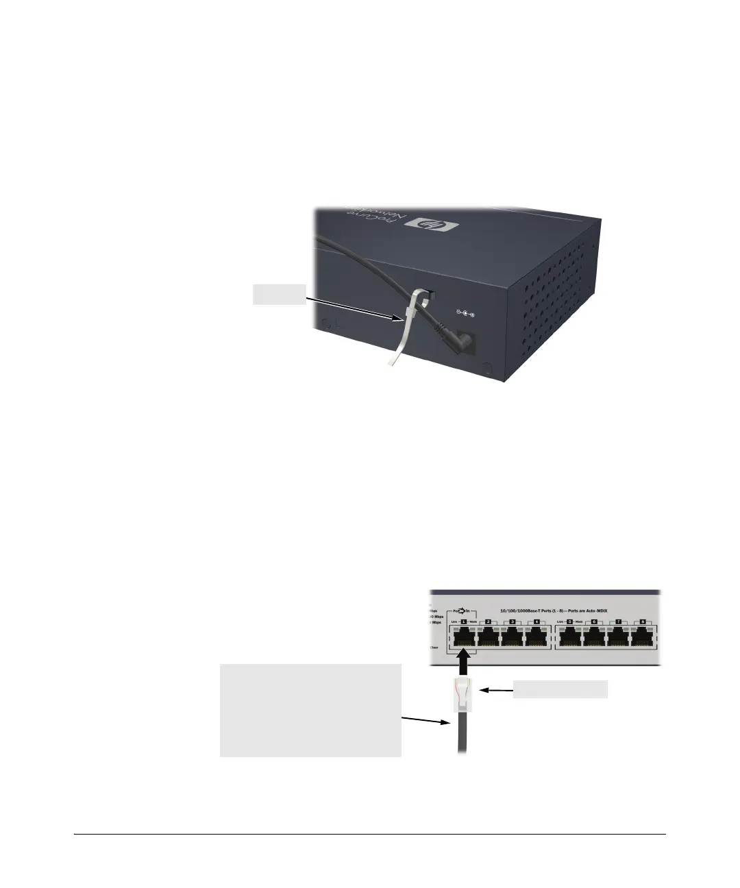
2. Use the included cable tie to secure the power cord to the switch.
3.) Re-check the LEDs during self test. See “Self Test LED Behavior” on
page 2-4.
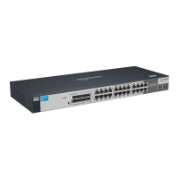
5. Connect the Network Cables
Push the RJ-45 plug into the RJ-45 jack until the tab on the plug clicks into
place. When power is on for the switch and for the connected device, the Link
LED for the port should light to confirm a powered-on device (for example,
an end node) is at the other end of the cable.
RJ-45 connector
100-ohm unshielded or shielded twisted-
pair cable:
• Category 3, 4, or 5 for 10 Mbps ports
• Category 5 only for 100 Mbps ports
• Category 5, 5e, or 6 for 1000 Mbps ports
Maximum distance: 100 meters
 Loading...