2-4
Installing the Switch
Installation Procedures
Installing the Switch
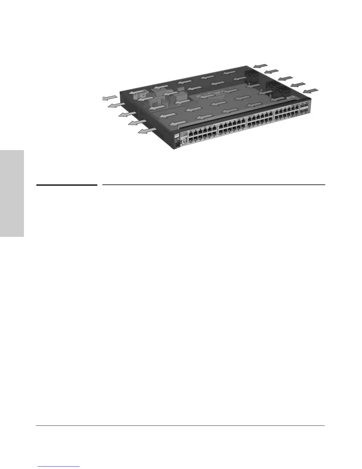
Figure 2-1. Air flow direction of the 2510G switch
Installation Procedures
Summary
Follow these steps to install the switch. The rest of this chapter provides
details on these steps.
1. Prepare the installation site (page 2-5). Ensure the physical environ-
ment is properly prepared, including having the correct network cabling
ready to connect to the switch and having an appropriate location for the
switch. Please see page 2-3 for some installation precautions.
2. Install mini-GBICs (optional—page 2-7). The switch has four slots for
installing mini-GBICs. Depending on where you will install the switch, it
may be easier to install the mini-GBICs first. Note that mini-GBICs can be
hot swapped—they can be installed or removed while the switch is
powered on.
3. Verify the switch passes self test (page 2-9). Plug the switch into a
power source and observe the LEDs on the switch’s front panel that they
indicate correct switch operation.
4. Mount the switch (page 2-11). The Switch 2510G Series devices can be
mounted in a 19-inch telco rack, in an equipment cabinet, on a horizontal
surface, or on the wall.
5. Connect power to the switch (page 2-14). Once the switch is mounted,
plug it into the nearby main power source.

 Loading...