2-5
Installing the Switch
Installation Procedures
Installing the Switch
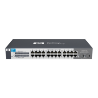
6. Connect the network cables (page 2-15). Using the appropriate
network cables, connect the network devices to the switch ports.
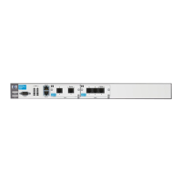
7. Connect a console to the switch (optional—page 2-16). You may wish
to modify the switch’s configuration, for example, to configure an IP
address so it can be managed using a web browser, from an SNMP network
management station, or through a Telnet session. Configuration changes
can be made easily by using the included console cable to connect a PC
to the switch’s console port.
At this point, the switch is fully installed. See the rest of this chapter if you
need more detailed information on any of these installation steps.
1. Prepare the Installation Site
■ Cabling Infrastructure - Ensure the cabling infrastructure meets the
necessary network specifications. See the following table for cable types
and lengths, and see appendix B, “Cables and Connectors” for more
information:
Table 2-1. Summary of Cable Types to Use With the Switch
Port Type Cable Type Length Limits
Twisted-Pair Cables
10/100/1000Base-T For either 10, 100 Mbps, or 1000 Mbps
operation:
Category 5 or better, 100-ohm UTP or shielded
twisted-pair (STP) balanced cable. For
1000 Mbps (gigabit) operation, Category 5E
cabling or better is recommended.
100 meters
Note: The Switch 2510G Series devices are
compatible with the IEEE 802.3ab standard
including the “Auto-MDIX” feature, which
allows use of either straight-through or
crossover twisted-pair cables for connecting
to any network devices including end nodes,
such as computers, or to other switches, hubs,
and routers.
Note: For 1000 Mbps operation, all four wire
pairs are used for data transmission.

 Loading...