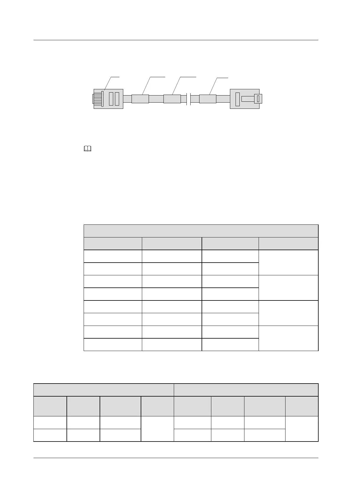
Figure 4-15 Structure of the network cable
W
X1 X2
8
1
8
1
RJ-45 network interface
connector
Label 1 Main label Label 2
NOTE
For a crossover cable, pins 1 and 2 of the RJ45 connector at one end must be cross-connected to pins 3 and
6 of the RJ45 connector at the other end respectively.
Pin Assignment
Table 4-29 and Table 4-30 list the pin assignment of the network cable connector.
Table 4-29 Pin assignment of the straight-through cable connector
straight-through Cable
Connector X1 Pin Connector X2 Pin Color Relationship
X1.1 X2.1 White-orange Twisted pair
X1.2 X2.2 Orange
X1.3 X2.3 White-green Twisted pair
X1.6 X2.6 Green
X1.4 X2.4 Blue Twisted pair
X1.5 X2.5 White-blue
X1.7 X2.7 White-brown Twisted pair
X1.8 X2.8 Brown
Table 4-30 Pin assignment of the crossover cable connector
Crossover Cable for FE Interface
Crossover Cable for GE Interface
Connecto
r X1 Pin
Connect
or X2 Pin
Color Relation
ship
Connector
X1 Pin
Connect
or X2 Pin
Color Relation
ship
X1.1 X2.3 White-orange Twisted
pair
X1.1 X2.3 White-orange Twisted
pair
X1.2 X2.6 Orange X1.2 X2.6 Orange
ATN 905 Multi-service Access Equipment
Product Description 4 Hardware Structure
Issue 01 (2013-05-30) Huawei Proprietary and Confidential
Copyright © Huawei Technologies Co., Ltd.
54
 Loading...