32
Speed control
The stop-right function
Driving of the motor
If the machine operates when the motor is connected
with a spare part circuit but not when the mounted circuit
is connected, remove the faulty circuit and send it in
for repair.
Comment 1
Note that the brusch holder and open wiring of the motor
and the rear of the printed circuit are live as soon as the
wall plug is connected. The switch does not de-electrify
the printed circuit. Make it a habit, therefore, to remove
the plug from the wall socket as soon as the belt guard
is removed and only reconnect when it is absolutely
necessary.
Comment 2
If the tube fuse is blown, this denotes that the printed
circuit is faulty. Do not replace the fuse-send in the
whole printed circuit for repair.
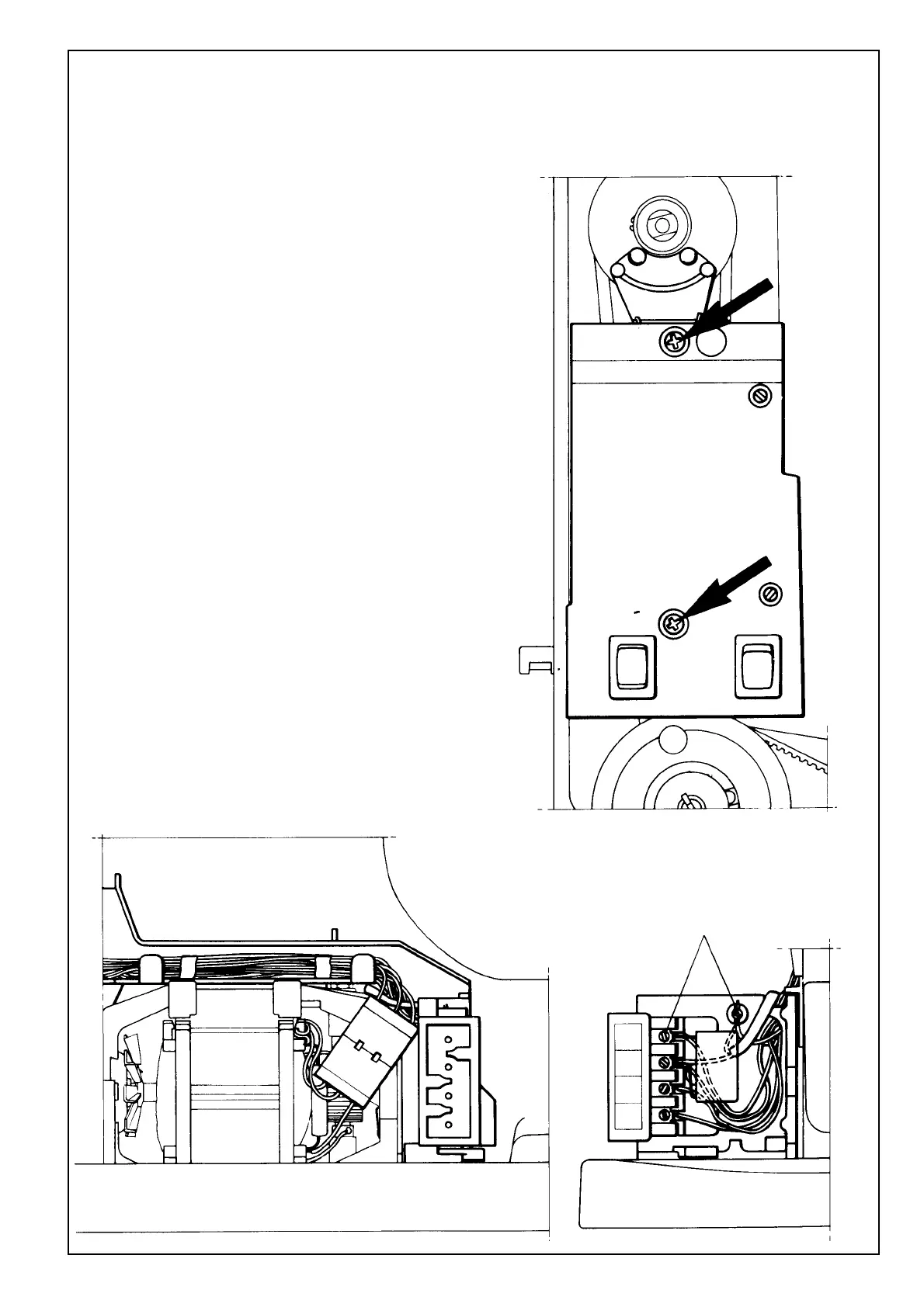
Removal
Loosen the 5 screws in the board which hold red, black,
white, yellow and blue wires. The lighting cable and
condenser (0.1 uF) should remain connected. Remove
the 2 screws (the cross-grooved screws) which hold the
printed circuit and separate the conductor joint at the
motor. Remove the cable protector from the wires and
push the wires through the hole in the terminal board.
Assembly
Assembly should be carried out in a corresponding way,
i.e. affix the cable protector and push the 5 wires back
through the hole in the terminal board. Note that the wires
must be connected to their respective colours. Replace
the printed circuit and press the conductor joint in.
 Loading...