6.18 The circuit boards and sensors
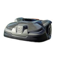
These are the circuits boards in the product:
• Main circuit board
• HMI circuit board
• Communication circuit board (Automower
®
connect
and GPS-module), 420/440 only as accessory
• Front loop circuit board
• Front collision circuit board
• Rear collision circuit board
• Lift sensor circuit board
• Cutting height circuit board
• Ultrasonic circuit board 450X/450XH/550/550H
The circuit boards contain the electronics and firmware
necessary to control the products functions.
The main circuit board, the HMI circuit board and the
communication circuit board contain their own separate
firmware. If any of these boards are replaced, they must
be programmed in Autocheck.
The other circuit boards do not have any firmware, and
do not need to be programmed after a replacement.
CAUTION:
Pull the connector and not the cable.
CAUTION: Do not touch the components or pin
terminals on the circuit board.
CAUTION: If the circuit board is to be checked
in order to evaluate the warranty, it must be
placed in a bag with protection against ESD
(electrostatic discharge).
CAUTION: Always protect the product from
electrostatic discharge, ESD, before you start to
work on electrical components.
6.18.1 To replace the main circuit board
The operating information of the product is stored in the
main circuit board. The Autocheck service program
saves this information in the log book and then transfers
it back to the product again when the main circuit board
has been replaced.
1. Connect the product to Autocheck before replacing
the main circuit board. The operating data is then
saved automatically.
2. Remove the body. Refer to
To remove and install
the body on page 20
.
3. Remove the upper chassis. Refer to
To remove and
install the upper chassis on page 20
.
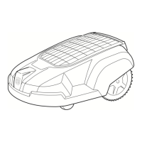
4. Disconnect the power cable/cables from the main
circuit board.
CAUTION: Always disconnect the power
cable first to prevent current spikes that may
harm the circuit boards or the battery.
5. Disconnect all the other cables from the main circuit
board.
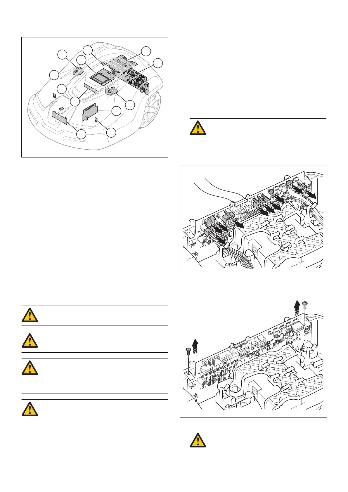
6. Remove the 2 screws and the 2 holders that hold
the main circuit board to the lower chassis.
7. Pull up the main circuit board and remove it.
CAUTION: If the board is to be checked in
order to evaluate the warranty, it must be
28 - Repair instructions 1191 - 001 -

 Loading...