Installation and maintenance manual
H.I.B Hydac International Page 23 of 36
Version: G/DV
Date: 11.01.2023
The operating equipment must be easily accessible. Between 0.6 and 1.9 metres (1.7
metres recommended) above the access level.
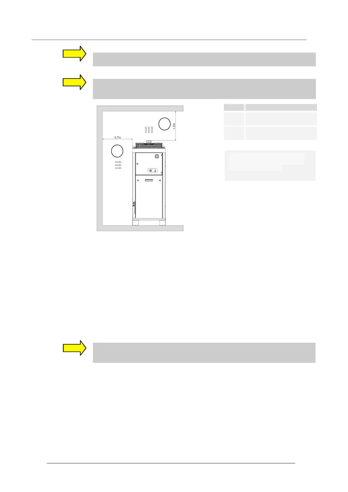
The cooling air must be able to circulate freely. Any air intake and outlet channels
must provide their own suction i.e. they must contain compensation bellows. The
fitting of air-conducting device has to be agreed with the manufacturer.
Air inlet
- S7/G7/G8 = 2,0m
Air outlet
- S7/G7/G8 = 5,0m
schematic diagram (see dimension sheet)
10.2 Hydraulic connection
The connections and the liquid circuits are to be positioned by experts in accordance with the
technical regulations.
The following must be observed:
Select suitable material for the hydraulic connection of the cooler
Select a suitable cross section to avoid pressure loss
Insulate tubes 5m long and over to prevent heat loss
If the consumer is located above the cooler, attach a solenoid valve in the return flow and
a non-return valve in the supply flow of the cooler. Reason: tank overflow
If parts of the cable or other connected elements are higher than the intended level of
liquid placed as the return flow of the coolant at a stationary plant is to be prevented
with proper facilities.
Recommended distance may be
less than for compressor / water
or water / water chiller.
 Loading...