AUXILIARY VALVES - SEKUNDÄRVENTILE
48
HCD3M-04
HC-D3M
38
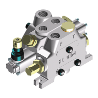
Sectional Valve - WEGEVENTIL IN SEKTIONSBAUWEISE
Ausführung der SekundärventileAuxiliary valves identification
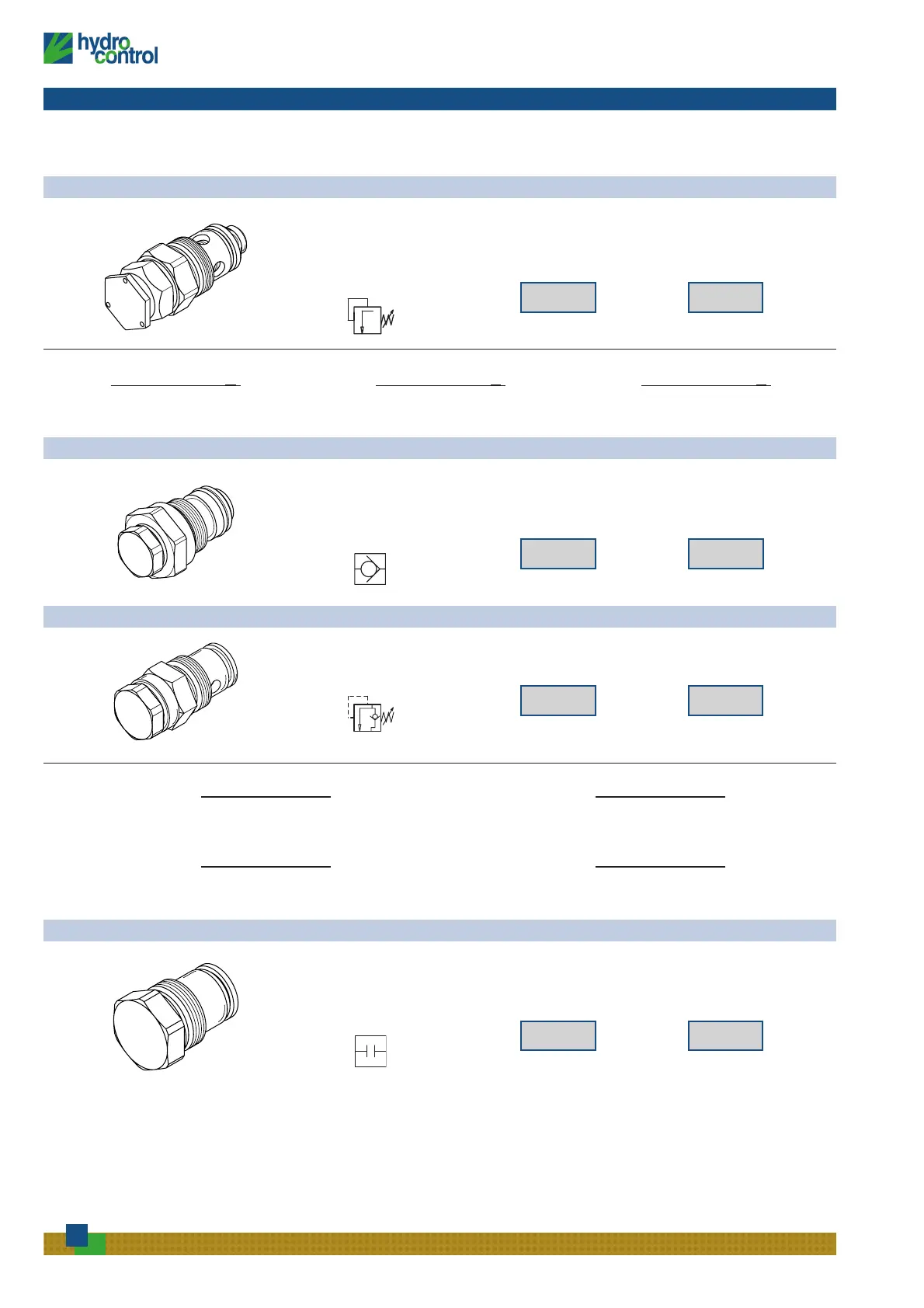
ANTISHOCK VALVE - SEKUNDÄRDRUCKBEGRENZUNGSVENTIL (ARV)
HYDRAULIC SCHEMA
HYDRAULIKSCHEMA
ORDERING CODES
BESTELLBEZEICHNUNGEN
01 PA 01 PB
port - Anschluss (A) port - Anschluss (B)
SETTING RANGES - EINSTELLBEREICHE (BAR)
Range -
Bereich (A) Range - Bereich (B)
20 / 60 (at full flow - bei max. Volumenstrom) 61 / 100 (at full flow - bei max. Volumenstrom)
10 / 40 (at min. flow - bei min. Volumenstrom)
41 / 80 (at min. flow - bei min. Volumenstrom)
Range - Bereich (C) Range - Bereich (D)
101 / 220 (at full flow - bei max. Volumenstrom) 221 / 350 (at full flow - bei max. Volumenstrom)
81 / 180 (at min. flow - bei min. Volumenstrom) 181 / 350 (at min. flow - bei min. Volumenstrom)
ANTICAVITATION VALVE - NACHSAUGEVENTIL
HYDRAULIC SCHEMA
HYDRAULIKSCHEMA
ORDERING CODES
BESTELLBEZEICHNUNGEN
02 PA 02 PB
port - Anschluss (A) port - Anschluss (B)
HINWEIS: Für Ventile, die den Einbau von Zubehörventilen vorsehen, ist
die Auswahl an den Anschlüssen A und B erforderlich. Geben
Sie beim Gebrauch von Sekundrädruckbegrenzungsventilen
auch stets den Einstellwert an:
EINSTELLWERT BEI MAX.VOLUMENSTROM = 01 PA 120
EINSTELLWERT BEI MIN.VOLUMENSTROM =01 PA 120-A
NOTE: sections designed to house auxiliary valve option require
double choice on work ports A and B.
Always indicate setting value when using antishock auxiliary valves
and cambinated valves:
SETTING AT FULL FLOW = 01 PA 120
SETTING AT MIN. FLOW = 01 PA 120-A
VALVE PLUGGED - VENTIL GESTOPFT
HYDRAULIC SCHEMA
HYDRAULIKSCHEMA
ORDERING CODES
BESTELLBEZEICHNUNGEN
05 PA 05 PB
port - Anschluss (A) port - Anschluss (B)
HYDRAULIC SCHEMA
HYDRAULIKSCHEMA
ORDERING CODES
BESTELLBEZEICHNUNGEN
03 PA 03 PB
port - Anschluss (A) port - Anschluss (B)
SETTING RANGES - EINSTELLBEREICHE (BAR)
Range -
Bereich (A) Range - Bereich (B) Range - Bereich (C)
20 / 100 (at full flow - bei max. Volumenstrom) 101 / 220 (at full flow - bei max. Volumenstrom) 221 / 150 (at full flow - bei max. Volumenstrom)
10 / 80 (at min. flow - bei min. Volumenstrom) 81 / 180 (at min. flow - bei min. Volumenstrom) 181 / 350 (at min. flow - bei min. Volumenstrom)
COMBINED VALVE - KOMBINIERTES VENTIL
 Loading...