ORDER MODALITY - BESTELLMODALITÄTEN
48
HCD3M-04
HC-D3M
4
Sectional Valve - WEGEVENTIL IN SEKTIONSBAUWEISE
BestellbeispielOrder example
AB C D
pag. / S. 13 pag. / S. 16 pag. / S. 44
HC-D3M/1 IR 001 (150) A G04 W001A H001 F001A RP G04 01PA(120) 05PB TJ A G04
A: AUSFÜHRUNG DES SEKTIONSWEGEVENTILS
D3M = Produktausführung
/1 = Anzahl der Wegeventilsektionen
B: ZUSAMMENSTELLUNG DER EINGANGSSEKTION
IR 001 = Eingangsseite und Ventilausführung Seite 13
150 = Einstellwert (bar)
A G04 = Eingangsposition und Gewindeart
C: ZUSAMMENSTELLUNG DER WEGEVENTILSEKTION
W001A = Kolben . . . . . . . . . . . . . . . . . . . . . .Seite 16
H001 = Kolbenbetätigung . . . . . . . . . . . . . . . .Seite 19
F001A = Kolbenrückführung . . . . . . . . . . . . . .Seite 23
RP G04 = Sektionsausführung und Gewinde .Seite 37
01PA120 = Sekundärventil (Anschluss A) . . .Seite 38
05PB = Stopfen (Anschluss B)
HINWEIS: Die Bestellreihe C muss für jede
Wegeventilsektion wiederholt werden.
.
D: ZUSAMMENSTELLUNG DER AUSGANGSSEKTION
TJ = Ausgangsausführung . . . . . . . . . . . . . . .Seite 44
A G04 = Ausgangsposition und Gewindeart
A: SECTIONAL CONTROL VALVE TYPE
D3M = product type
/1 = number of sections
B: INLET ARRANGEMENT
IR 001= inlet side and valve type . . . . . . . . . .page13
150 = setting (bar)
A G04 = inlet position and available thread type
C: WORK SECTION ARRANGEMENT
W001A = spool . . . . . . . . . . . . . . . . . . . . . . . .page16
H001 = spool actuation . . . . . . . . . . . . . . . . . .page 19
F001A = spool return action . . . . . . . . . . . . . .page 23
RP G04 = type and thread section . . . . . . . . .page37
01PA120 = auxiliary valve (port A) . . . . . . . . .page38
05PB = valve plugged (port B)
NOTE: ordering row C must be repeated for every work
section.
D: OUTLET ARRANGEMENT
TJ = outlet type . . . . . . . . . . . . . . . . . . . . . . .page44
A G04 = outlet position and available thread type
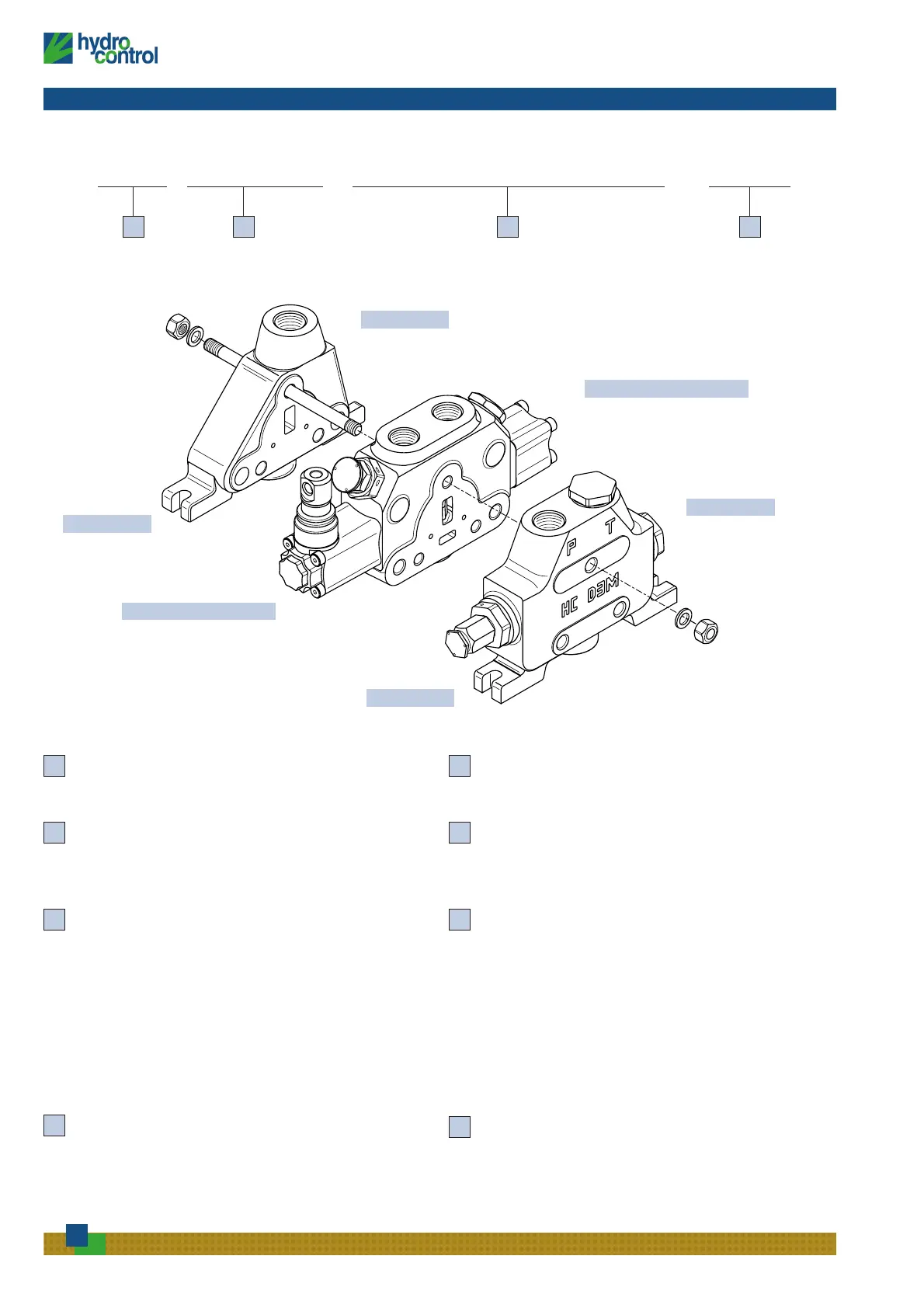
WEGEVENTILSEKTION
AUSGANG
EINGANG
WORK SECTION
OUTLET
INLET
 Loading...