SETUP
3-14 CommandTHC for X-Y Table Instruction Manual
6
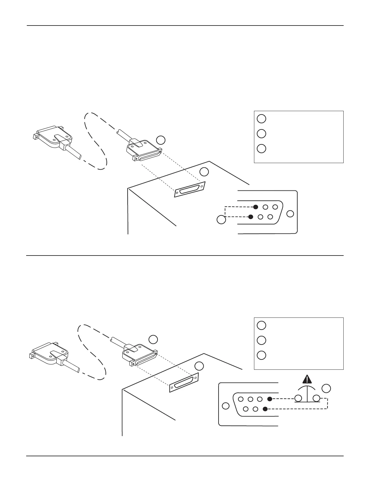
Machine interface cable
1. Cable-installed signal – See Figure 3-9.
The machine interface cable provides a signal to verify that the cable is installed properly. Continuity must be
provided through pins 3 and 22 so that the signal is not interrupted.
Install a jumper wire in the CNC to provide continuity between pins 3 and 22 when the machine interface cable is
installed to the CNC receptacle.
2. Emergency stop signal – See Figure 3-10.
The machine interface cable provides a signal for emergency stop. Continuity must be provided through pins 16 and
35 so that the signal is not interrupted.
Install a normally closed switch in the CNC to provide continuity between pins 16 and 35 when the machine
interface cable is installed to the CNC receptacle.
 Loading...


