EasyManua.ls Logo

Hypertherm Powermax 85 Service Manual

Hypertherm Powermax 85
248 pages
To Next Page IconTo Next Page
To Previous Page IconTo Previous Page
Page #111 background image
OperatiOn
powermax
65/85
Service Manual 4-9
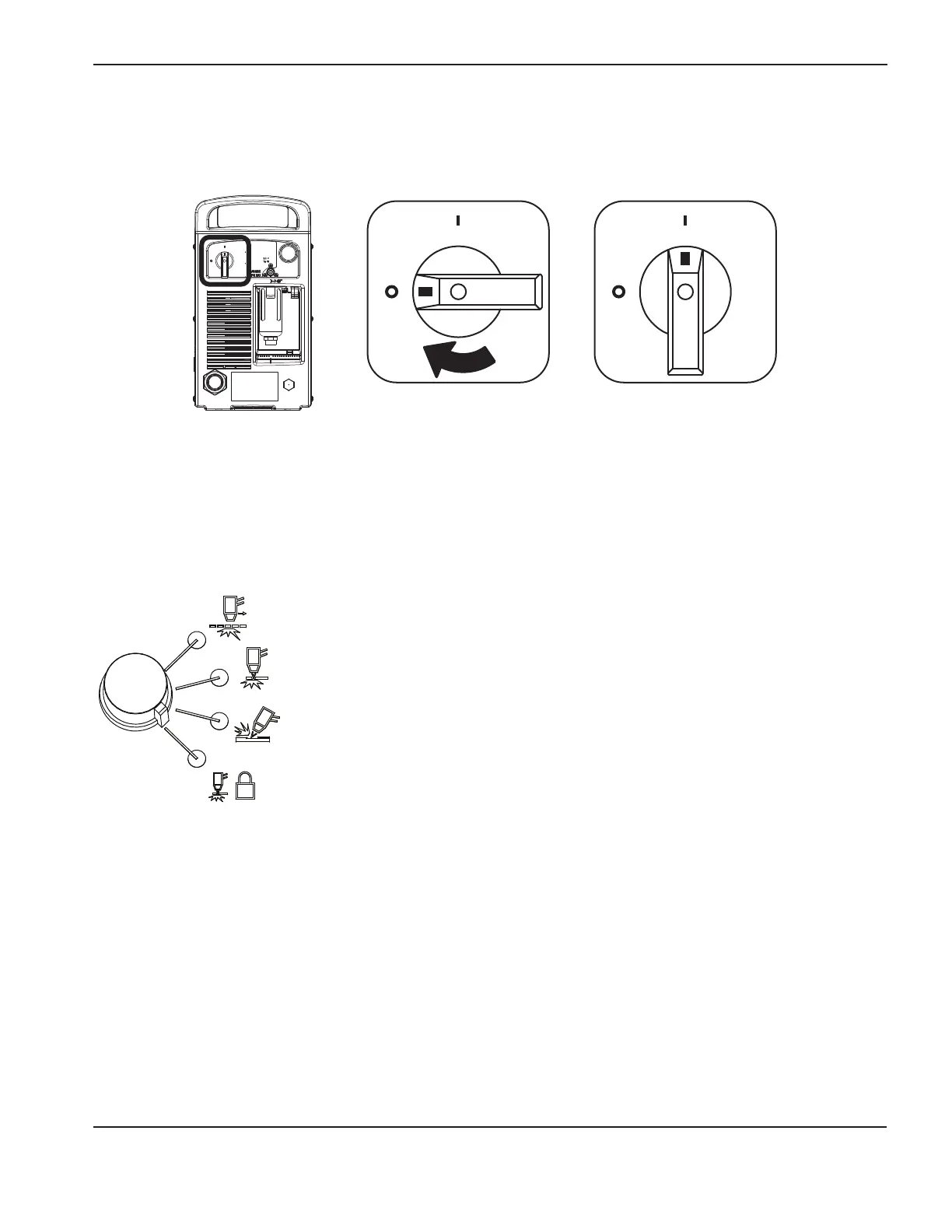
Set the operating mode switch
Use the operating mode switch to select the type of work you want to perform.
In automatic gas mode, Smart Sense™ technology automatically adjusts the gas pressure according to the selected
cutting mode and torch lead length for optimum cutting.
For cutting expanded metal, grates, metal containing holes, or any job that requires a
continuous pilot arc. Using this mode to cut standard metal plate reduces consumable
life.
For cutting or piercing metal. This is the standard setting for normal drag-cutting.
For gouging metal. (Note: Using this mode while cutting results in poor cut quality.)
Locks the torch in the ON (fire) position. With this option selected, press the trigger to
fire the torch. You can then release the trigger while continuing to cut. Press the trigger
again to stop the arc. The arc also stops if you lose transfer.
Turn ON the system
Set the ON/OFF switch to the ON (I) position.
Off
On

Table of Contents

Other manuals for Hypertherm Powermax 85

Questions and Answers:

Hypertherm Powermax 85 Specifications

General IconGeneral
Gas SupplyClean, dry, oil-free air or nitrogen
Cooling MethodFan-cooled
Input Voltage200-600V, 3-phase
Current Output25-85 A
Duty Cycle60% @ 85 A
Recommended Gas Inlet Flow Rate/Pressure6.7 scfm @ 85 psi
Cutting Capacity (Recommended)1" (25 mm)
Gas TypeAir/Nitrogen

Summary

WARRANTY

General Warranty Information

Outlines warranty periods for power supplies, torches, and components.

Section 1 SPECIFICATIONS

Power Supply Ratings

Details electrical ratings for Powermax65 (voltage, current, duty cycle, power factor).

Cutting Specifications

Provides cutting capacities, speeds, and gouging rates for Powermax65/85.

Section 3 TORCH SETUP

Cutting Data and Specifications

Provides cut charts and kerf-width compensation data for various applications.

Section 4 OPERATION

Controls and Indicators

Describes the front and rear controls, LEDs, and status screen of the power supply.

System Operation Steps

Guides on connecting power, gas, torch, and attaching work leads/clamps.

Adjusting Settings and Limitations

Explains gas pressure, current adjustments, and duty-cycle limitations.

Hand Torch Usage

Covers safety trigger, cutting hints, starting cuts, piercing, gouging, and faults.

Machine Torch Usage

Details machine torch setup, cut quality optimization, piercing, and common faults.

Section 5 TROUBLESHOOTING AND SYSTEM TESTS

Troubleshooting Overview

Covers controls, theory of operation, sequence, prep, and procedures for troubleshooting.

System Checks and Fault Diagnosis

Details inspections, resistance checks, fault codes, icons, and solutions.

Component-Specific Tests

Outlines tests for voltage input, DC power buss, diodes, sensors, flyback circuit, and switches.

Section 8 WIRING DIAGRAMS

Electrical Schematic Diagrams

Presents electrical schematic diagrams for CSA and CE configurations.

Related product manuals