TroubleshooTing and sysTem TesTs
powermax
45
Service Manual 5-27
Test 7 – torch cap sensor
Test the cap-sensor switch and torch leads.
1. Set the ON/OFF switch to OFF(O).
2. Measure the resistance between pins1 and2 of J10 on the power board. It should measure less than10 Ω. If it
reads as open, the cap-sensor switch circuit is not satisfied.
3. If the torch plunger moves smoothly and the consumables are correctly installed, then either the cap-sensor switch
is faulty or the torch lead has a broken wire. Replace the faulty part.
Test 8 – fan
Test the fan for proper operation.
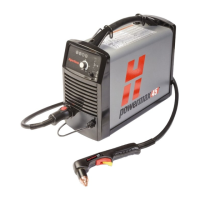
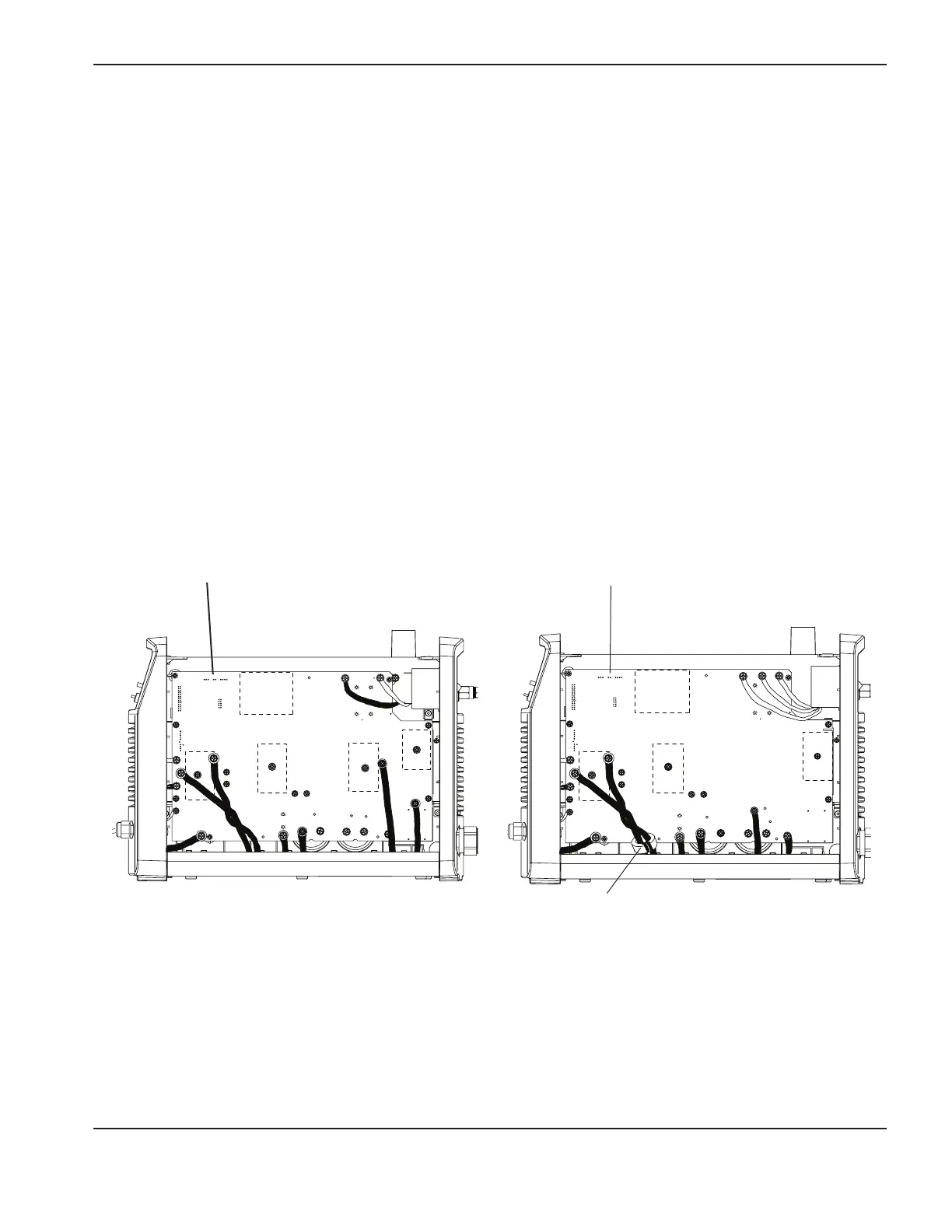
• Place a jumper from pin1 of J3 to pin1 of J4 on 200–240V CSA power supplies and 230V CE power supplies
or from pin1 of J4 to pin1 of J5 on 400V CE and 480V CSA power supplies. If the fan does not operate,
replace the fan.
NOTE: Testing the fan can trigger a fault due to protection features on the fan driver chip. You can disregard
this fault if it occurs as a result of a fan test. The purpose of the fan test is to ensure the fan is operating
properly, not to test the fan drive circuit.
TP 19
W
-
+
-
+
TP 18
R
TP 17
B
192 VDC
192 VDC
TP17
W
+
-
+
-
TP18
B
TP16
R
~280 VDC
~280 VDC
J3 and J4
J4 and J5
200–240V CSA and 230V CE
power supplies
400V CE and 480V CSA
power supplies
(Ferrite found on CE units only)
 Loading...


