TroubleshooTing and sysTem TesTs
5-20 powermax
45
Service Manual
Note: To test the values at pin 16, you must have the torch and power supply positioned such that you can safely pull
and release the torch’s trigger.
Test 3 – VBUS and voltage balance
Test the power board to ensure that the circuits are balanced. There are three procedures below. Use the first
procedure if you have a 200–240V CSA power supply or a 230V CE power supply. Use the second procedure if you
have a 400VCE power supply. Use the third procedure if you have a 480V CSA power supply.
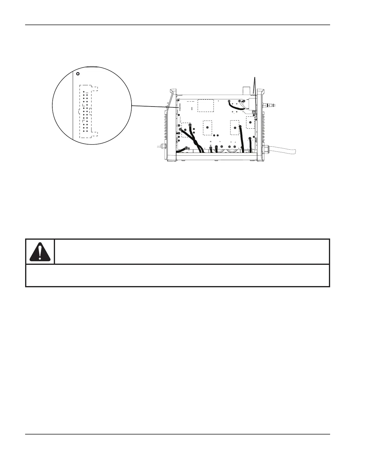
For this test, you can use the test point loops or you can test on the capacitor screws. The test points are labeled on the
back of the power board, as are the voltages and positive and negative capacitor terminals.
CAUTION
To test using the test points, do not use a multimeter with test probes. Use E-Z Hook leads instead
and attach them to the test point loops.
J7 (200–240V CSA / 230V CE)
J8 (400 V CE / 480V CSA)
1
2
25
26
Ground to the ground wire clip or to the heat sink
TP 19
W
-
+
-
+
TP 18
R
TP 17
B
192 VDC
192 VDC
 Loading...


