Wiring Diagrams
powermax
45
Service Manual 8-3
12
34
56
78
910
11 12
13 14
15 16
17 18
19 20
21 22
23 24
25 26
CAPOFF1
YEL
"TSO/TSC"
FAULT1
YEL
1
2
3
4
JTAG1
1
3
5
7
9
11
13 14
2
4
6
8
10
12
AC PWR1
GRN
"L/H LINE"
720
IN
15
IN
9
V-
8
IN
7
IN
13
IN
12
IN
11
IN
10
IN
6
V+
16
IN
3
IN
2
IN
1
IN
5
IN
14
IN
4
AMPS1
CW
TEMP1
YEL
2
1
3
4
56
7
ON
ON
CASE
CASE
GRN
L
R
1
ERROR
CODE
.25"
FOR
BD
DEPAN-
IZATION
SERIAL
DATA
MACHINE
FRONT
DSP 2806
4x25Mhz=100Mhz
0.78 x 0.78"
Stayout for
TEST CLIP
/RESET or
HDR FLT
START
XFR
GAS
CONTROL PWA
45 A 400 V SYS
MODE
CPA (UP)
NORMAL (MIDDLE)
GOUGE (DOWN)
YEL
YEL
GRN
"SETPOINT"
GRN
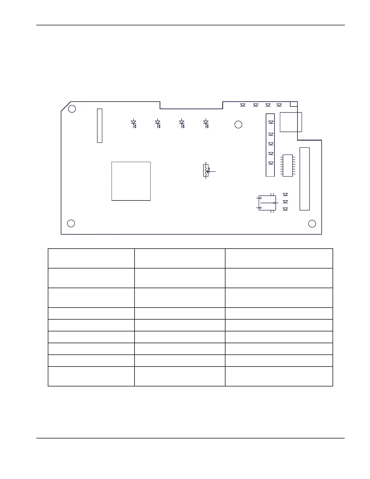
Control board diagram: 400V CE and 480V CSA
J8 pin number to ground Test
Expected value
(400V CE or 480V CSA)
19 VACR (rectified AC line voltage)
2.7V at 400 line voltage (CE)
2.016VDC at 480 line voltage (CSA)
21 VBUS (DC bus voltage)
2.178VDC at 560VBUS (CE)
2.016VDC at 670VBUS (CSA)
20 IFB (output current) < 0.1VDC
22 ITF (transfer current) < 0.1VDC
25 3.3VDC 3.3VDC ±5%
24 5VDC 5VDC ±5%
12 24V sense pin 2.2VDC
16 Start signal
3.2 VDC closed
0 VDC open
 Loading...


