torch setup
powermax
45
Service Manual 3-29
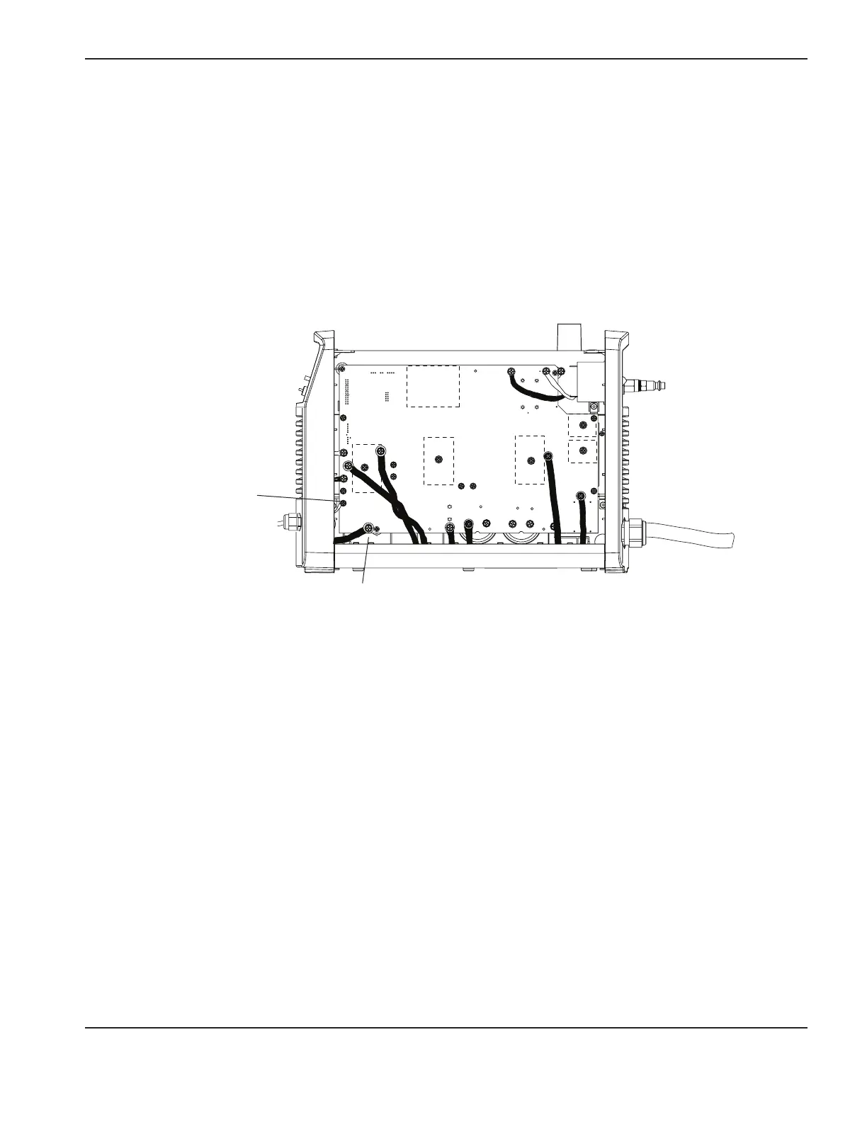
10. Route the wires along the base of the unit and behind the cables connected to the power board.
11. Remove the work lead connector screw at J21 and the white wire connector screw at J19 (J18 for 400V CE and
480V CSA power supplies).
12. Connect wire1 to J19 (J18 for 400V CE and 480V CSA power supplies) with the ring connector for wire1
closest to the power board and the connector for the white wire closest to the head of the screw. Turn the ring
connector for wire1 upside down so that the slight bend in the ring connector base creates a little space between
the wire and the board. Tighten the screw to 23.0kgcm (20 inch-pounds).
13. Connect wire2 to J21. This time, put the connector for the work lead closest to the power board and put the ring
connector for wire2 closest to the head of the screw. Torque the screw to 23.0kgcm (20 inch-pounds).
14. Replace the rear panel and secure it with the screw. Replace the Mylar barrier in front of the power board. Replace
the cover.
15. Connect the other end of the cable to the equipment according to the manufacturer’s instructions.
NOTE: The integration of Hypertherm equipment and customer-supplied equipment including interconnecting
cords and cables, if not listed and certified as a system, is subject to inspection by local authorities at the
final installation site.
TP 19
W
-
+
-
+
TP 18
R
TP 17
B
192 VDC
192 VDC
J21 (work lead)
J19 or J18
(white wire)
 Loading...


