TABLE OF CONTENTS
Operator Manual
vi
ILLUSTRATIONS
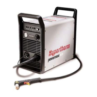
Figure 2-1 Powermax900 Hand Plasma Cutting System............................................................. 2-2
Figure 2-2 Powermax900 Power Supply with Dimensions .......................................................... 2-3
Figure 2-3 PAC125T Torch with Dimensions ............................................................................... 2-4
Figure 2-4 PAC125M Torch with Dimensions............................................................................... 2-4
Figure 3-1 Powermax900 Power Supply Hoisting Setup ............................................................. 3-3
Figure 3-2 Rear Panel.................................................................................................................. 3-4
Figure 3-3 200V or 208V Configuration ....................................................................................... 3-5
Figure 3-4 230V or 240V Configuration ....................................................................................... 3-5
Figure 3-5 400V or 480V Configuration ....................................................................................... 3-5
Figure 3-6 Power Cord Preparation ............................................................................................. 3-6
Figure 3-6a Power Cord Preparation - CE ..................................................................................... 3-6
Figure 3-7 Single-Phase Power ................................................................................................... 3-7
Figure 3-8 Three-Phase Power - Non-CE.................................................................................... 3-7
Figure 3-9 Three-Phase CE Power.............................................................................................. 3-8
Figure 3-10 Proper Work Clamp Connection ................................................................................. 3-9
Figure 3-11 Recommended Three-Stage Air Filtration System ................................................... 3-10
Figure 3-12 Rear Panel, Gas Supply Connection to Filter ........................................................... 3-11
Figure 3-13 ON/OFF Pendant Connection .................................................................................. 3-12
Figure 3-14 Aligning the Machine Torch with Square .................................................................. 3-13
Figure 3-15 Machine Interface Cable and Signals ....................................................................... 3-13
Figure 3-16 Feeding Arc Voltage Cable to Machine Interface Board ........................................... 3-14
Figure 3-17 Machine Interface Board Connections for Arc Voltage ............................................. 3-14
Figure 4-1 Powermax900 Controls and Indicators....................................................................... 4-2
Figure 4-2 Powermax900 Operating Indicators and Adjustments................................................ 4-3
Figure 4-3 Proper Work Clamp Connection ................................................................................. 4-4
Figure 4-4 PAC125T Torch Safety Trigger Operation .................................................................. 4-5
Figure 4-5 Consumables.............................................................................................................. 4-7
Figure 4-6 Starting a Cut.............................................................................................................. 4-8
Figure 4-7 Cutting a Circle ........................................................................................................... 4-9
Figure 4-8 Dragging the Torch ..................................................................................................... 4-9
Figure 4-9 Piercing..................................................................................................................... 4-10
Figure 4-10 Gouging .................................................................................................................... 4-11
Figure 5-1 Filter Assembly ........................................................................................................... 5-2
Figure 5-2 Air Filter Removal ....................................................................................................... 5-3
Figure 5-3 Shielded Consumable Configurations ........................................................................ 5-8
Figure 5-4 Unshielded Consumable Configurations .................................................................... 5-8
Figure 5-5 PAC125T Torch Assembly and Leads ........................................................................ 5-9
Figure 5-6 PAC125M Torch Assembly and Leads...................................................................... 5-10
Figure a-1 F1 and F2 Fuse Location............................................................................................ a-1
Figure c-1 Aeration Manifold........................................................................................................ c-1

 Loading...


