Connect for Communication
XPR300 Instruction Manual 809480 165
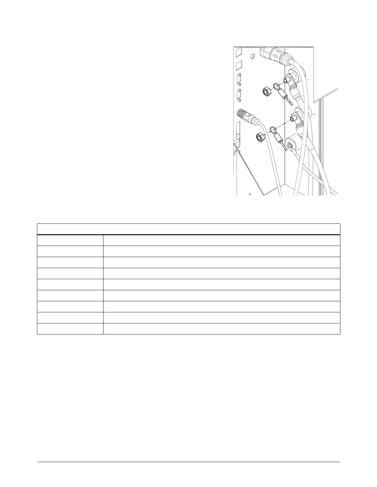
6. Attach the ring connector on the yellow wire (WORK)
to the work bolt in the plasma power supply.Tighten the
nut to 20 Nm (15 ftlb).
7. Attach the ring connector on the yellow/black wire
(NEG) to the negative bolt in the plasma power supply.
Tighten the nut to 20 Nm (15 ftlb).
Other wires are already attached to the bolts in
the plasma power supply. Attach the arc voltage
wires on top of the existing wires.
8. Use NCS (pin 3), NCE (pin 4), Aout+ (pin 6), and
Aout- (pin 7) to connect to the CNC. Refer to
Figure 45 on page 160 for the locations of the pins.
Refer to Table 27 for the pinout.
Use the interface requirements of your CNC for
additional connection requirements.
Table 27 – Pinout for J2 on the VDC3 board
9. Install the rear panel of the plasma power supply.
J2 on the VDC3 board
Pin number Signal
1 Not connected
2+24VDC (out)
3 Nozzle contact sense (output)
4 Nozzle contact enable (input)
5 24 VDC common
6+ Analog out (40:1)
7 - Analog out (analog common)
8 EMI chassis ground (cable shield)

 Loading...


