1-5
INSTALLATION
SFC BOILER / WATER HEATERS - SFC 199
1.4 EXHAUST VENTING AND AIR INTAKE
When you plan the installation, ensure that you consider appropriate venting
materials, travel and termination decisions. In particular, you should manage the
impact of the steam plume typically at the exhaust terminal of a condensing unit.
Generally, intake and exhaust pipes terminate at a rooftop or sterile wall location.
Keep exhaust plumes well away from all building air intakes including those of
neighbouring properties.
Install venting in accordance with the requirements of the jurisdiction having
authority: in Canada, Part 8, Venting Systems of the B149.1-10 Code and any
other local building codes are to be followed. In the USA the National Fuel Gas
Code, ANSI 223.1, latest edition, prevails. Where there is a discrepancy between
the installation instructions below, and the code requirements, you must apply the
more stringent of the two.
Provisions for combustion and ventilation air in accordance with the section “Air
for Combustion and Ventilation,” of the National Fuel Gas Code, ANSI Z223.1/
NFPA 54, or Clause 8.2, 8.3 or 8.4 of Natural Gas and Propane Installation Code,
CAN/CSA B149.1, or applicable provisions of the local building codes.
IMPORTANT
When an existing unit is removed from a common venting system, the common
venting system is likely to be too large for proper venting of the appliances
remaining connected to it.
When re-sizing any portion of the common venting system, the common venting
system should be re-sized to approach the minimum size as determined using
the appropriate tables in the National Fuel Gas Code, ANSI Z223.1 - latest
edition. In Canada, use the B149.1 Installation Code - latest edition.
WARNING
Venting, condensate
drainage, and combustion
air systems for all IBC units
must comply with applicable
codes and the instructions of
their respective Installation
manuals.
Inspect nished vent and air
piping thoroughly to ensure
all are airtight and comply
with the instructions provided
and with all requirements of
applicable codes.
Failure to comply will result
in severe personal injury or
death.
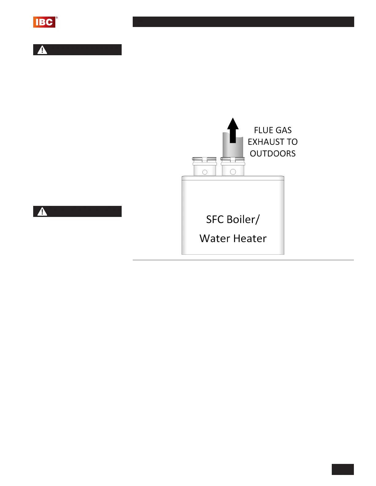
Figure 3: Basic exhaust vent assembly
NOTES
The minimum thickness of the
wall for venting penetration
is 1” and the maximum
thickness for venting is 14”.
Do not connect a water heater
to a chimney ue serving a
separate appliance designed
to burn solid fuel.
The air intake tting can be
moved to the left or to the
right of the exhaust tting.
 Loading...