INSTALLATION AND OPERATION INSTRUCTIONS
4-4
SFC BOILER / WATER HEATERS - SFC 199
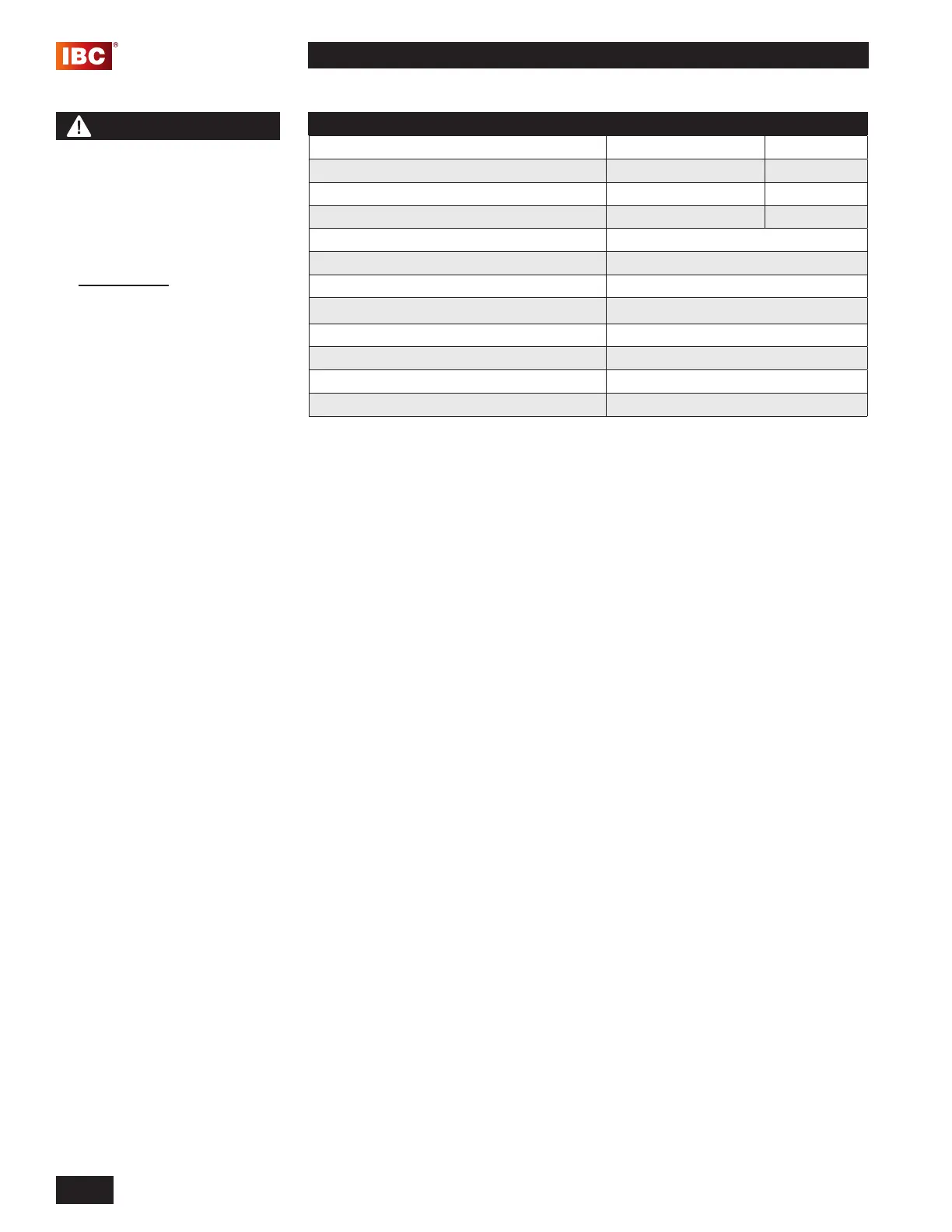
DESCRIPTION MAX MIN
Water Pressure 150 psi 40 psi
Programmable water temperature 149°F (65°C) 104°F (40°C)
Minimum Flow Rate to Activate DHW Sensor N/A 0.5 GPM
Acceptable pH range 8.5 pH 6.5 pH
Total Dissolved Solids 500 mg/L
Total Hardness 200 mg/L 11.68 gr/gal
Aluminum 0.05 to 0.2 mg/L
Chlorides 250 mg/L
Copper 1.0 mg/L
Iron 0.3 mg/L
Manganese 0.05 mg/L
Zinc 5 mg/L
Table 13: Domestic Water Quality Guidelines
4.1.15 Fan and gas valve removal instructions
1. Turn off the power and the gas supply to the unit.
2. Remove the front cover, and allow the unit to cool down.
3. Disconnect the electrical plug attached to the fan.
4. Loosen the union nut at the top of the gas valve. Carefully remove the orice
and O-ring, and keep in a safe place for re-installation later. Ensure you
protect the gas valve outlet from dust and debris.
5.
Remove the 2 mm hex nuts connecting the fan to the burner housing, and
carefully remove the fan. You will nd a gasket attached to the fan outlet as
well as an internal check valve. Keep these items in a safe place for re-
installation.
6. If the removed fan is to be re-installed, ensure the fan and venturi are clean
and dust free. If the fan is being replaced, move the venturi over to the new
fan. Note that the t is tight.
4.1.16 Fan and gas valve re-assembly instructions
1. Place the fan gasket on the outlet of the fan housing. The gasket has 2
locator pins to ensure the gasket does not move during installation.
2. Place the check valve on the fan gasket, and attach the fan to the burner
housing and install the 2 mm hex nuts. Tighten the 2 hex nuts with a wrench.
3. Insert the orice and O-ring between the gas valve outlet and the gas line to
the fan. Tighten the gas valve union nut with a wrench. Ensure that the gas
valve inlet (lower) nut is tight.
4. Connect the electrical plug to the fan.
5. Restore the gas supply to the unit, and test the gas valve inlet for gas leaks.
6. Restore the power to the unit, and create a call for heat or hot water.
7. Check for leaks at the gas valve outlet and the connection between the fan
and the burner housing.
8. Install the cover to the unit.
9. Reset the unit to normal operation.
DANGER
When servicing or replacing
the fan, you must transfer the
venturi from the old fan to the
new fan.
Failure to relocate the venturi
to the new fan may cause
an immediately hazardous
situation which must be
avoided in order to prevent
serious injury or death.
 Loading...