2-7
BOILER SYSTEMS AND OPERATION
SFC BOILER / WATER HEATERS - SFC 199
2.7 SEQUENCE OF OPERATION
The unit operates in a similar way for both a space heating and a domestic hot
water call for heat. When the unit is powered up the controller enters a self-
diagnostic mode, and displays “2” in the Service Display.
The sequence of operation is as follows:
1. The unit receives a call for heat from closing terminals X13.1 and X13.2
(24 volts section). The unit can also receive a call from domestic hot water
heating from the internal ow sensor, or from a 10KΩ sensor or aquastat
(X13.4 and X13.5 in 24V terminal).
2. The unit does a safety check and energizes the fan for a pre-purge (Service
Display = 3).
3. Once the 5-second pre-purge is compete, the unit enters a 5-second trial for
ignition (Service Display = 4). If the unit fails to ignite, the unit will complete
a 5-second inter-purge then another 5-second trial for ignition. This is
repeated 4 times before a hard lock-out occurs. The Return button must
be pressed to reset the controller and to allow for another attempt.
4. Once the burner is lit and ame has been proven the unit operates as it is
programmed (Service Display = for space heating or for domestic
hot water).
5. If the unit reaches its target temperature and there is still a call for heat or hot
water the burner will turn off (integral pump runs unless call is on-demand
DHW). (Service Display = 1)
6. After the call for heat is satised, the unit’s pump will operate for an
adjustable amount of time (Service Display = 0).
7. If the burner is on to maintain the heat exchanger temperature for DHW
Comfort mode (Service Display = 7).
8. If the burner is on for frost protection (Service Display = 9).
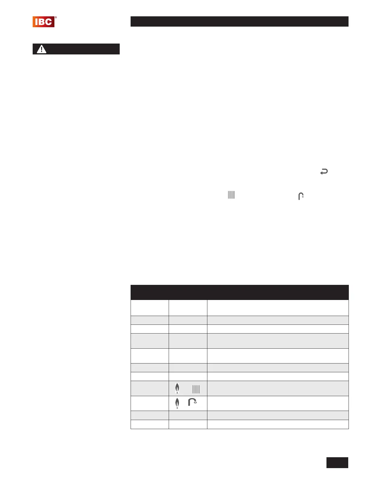
MAIN
DISPLAY
LIT
DISPLAY
DESCRIPTION
[pressure] P - The unit is OFF. Press the space above the white button
to turn on the unit.
(blank) (blank) No Call for Heat - Standby
XXX 0 Unit pump running – pump post purge
XXX 1 Unit water temperature reached target – unit pump is
energized, call for heat still present
XXX 2 Self-test – When power is applied to the unit the
controller enters a self diagnostic mode for 5 seconds
XXX 3 Fan Pre-purge , Inter-purge and Post-purge
XXX 4 Trial for Ignition and Flame Proving
XXX
+
Heating – Space Heating
XXX
+
Heating – DHW
XXX 7 Burner on for Comfort mode
XXX
9
Freeze Protection mode
Table 10: Operating Display and Service Display Codes.
NOTE
The unit is equipped with a
frost protection feature. This
feature operates the unit’s
pump and the burner to help
protect the unit from freezing.
If the unit is in a hard lock-
out condition the burner will
not operate, but the unit’s
pump will operate. IBC is
not responsible for damages
to the unit, and/or related
components, nor property
damages that may result from
freezing conditions.
 Loading...