INSTALLATION AND OPERATION INSTRUCTIONS
1-36
SFC BOILER / WATER HEATERS - SFC 199
1.9.2 Power Quality and Electrical Protection
In areas of unreliable power, appropriate surge protectors and / or power
conditioning equipment should be installed to protect the unit.
1.9.3 Zone Valve and Zone Pump Connections
Zoning can be accomplished with either zone pumps or zone valves. If zoning by
multiple pumps, we recommend using an external pump module.
Zone valve end switches can be wired together in parallel, and connected to X13
terminals 1 and 2. Do not apply power to the X13 terminal strip. Alternatively, you
can connect the zone valves and thermostats to a zoning panel control system
(available from your local heating wholesaler).
You can connect zone pumps to the unit with a zone pump control, available from
your local heating wholesaler.
1.9.4 Thermostat / Sensor Wiring
A thermostat from a single zone heating system can be connected directly to the
controller’s X13 terminals 1 and 2. Do not apply power to the X13 terminal strip.
An outdoor sensor is not required for the unit to operate. If an outdoor sensor is
not connected, the unit will operate as a set point unit and operate at its design
supply temperature.
If outdoor reset functionality and the summer shut-down feature are desired
connect the supplied Outdoor sensor to X13 terminals 3 and 4. The outdoor
sensor is a 12KΩ thermistor type sensor.
The sensor should be installed:
• On the exterior of the building on the north side.
• So that it is not affected by any heat sources from the building such as a dryer
or exhaust fan outlet, relief air or combustion air grill above a window or door,
or mounted directly under a deck or soft overhang.
DHW Aquastat or 10KΩ sensor can be connected to the controller’s X13
terminals 4 and 5. Do not apply power to the X13 terminal strip.
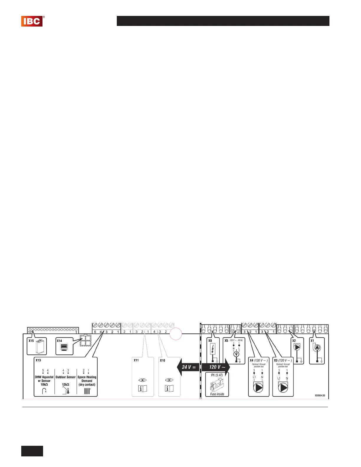
Figure 38: Terminal strip for connection of the DHW Aquastat (optional), thermostat or end switch(es) (mandatory), outdoor sensor
(optional)
 Loading...