Home
IBM
Desktop
Aptiva
IBM Aptiva Hardware Maintenance Guide
5
of 1
of 1 rating
282 pages
Give review
Manual
Specs
To Next Page
To Next Page
To Previous Page
To Previous Page
Loading...
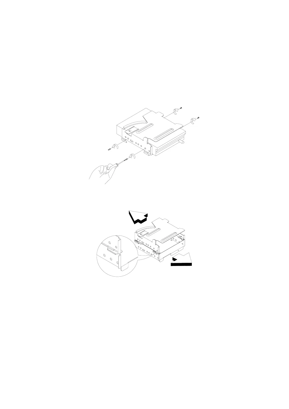
Repair Information
4-11
•
Remove screws for drive, then pull the drive out.
Figure 4- 9
Remove the drive
•
If upper and lower frames needs to be detached (Machine Type 2137),
please refer to fi
gure 4-10.
Figure 4- 10
Detach drive frame
113
115
Table of Contents
Default Chapter
3
Table of Contents
3
Notices
7
Voltage Supply Switch Settings
7
Safety Information
8
Safety Notices (Multi-Lingual Translations)
9
Laser Compliance Statement
13
Federal Communications Commission (FCC) Notice
14
Federal Communications Commission (FCC) Statement
14
Canadian Department of Communications Compliance Statement
15
Canadian Department of Communications Certification Label
15
Trademarks
16
General Information
18
General Information
19
Introduction
19
Product Overview
19
Hardware Interfaces
25
Memory Map
27
System Input / Output Addresses
27
System Interrupts
29
DMA Channel Assignments
30
Serial Port Addresses
30
Parallel Port Addresses
31
Refresh Rates and Monitor Frequencies
31
CMOS Reset
31
Power-On Password
32
BIOS-Contained Model Number and Serial Number
33
Flash (BIOS) Update Procedure
34
BIOS Setup Utility
35
Working with the Setup Menus
35
Viewing System Information and Product Data
38
Disk Drives
38
Devices and I/O Ports
40
Power Management
42
Startup Options
44
Date and Time
45
Advanced Options
45
Specifications
51
Operating Requirements
53
Special Tools
53
Check Procedures
55
Introduction
55
Check Procedures
56
Start
56
Index of Symptoms, Messages, Error Codes, or Beeps
61
Check Procedures
64
Check Procedures
79
Factory-Installed Storage Devices
80
Factory-Installed Modem Card
83
Audio (Not Supported by Diagnostics Program)
85
CD-ROM Drive
87
Memory
88
Keyboard
89
Mouse
90
Power Supply
92
Monitor
95
Undetermined Problems
97
Diagnostic Aids
98
Diagnostic Aids
99
Introduction
99
Power-On Self Test
99
Diagnostic Diskette
100
Diagnostics Program Features
100
Using the Diagnostic Diskette
102
Using Diagnostic Program from Recovery CD
103
Repairing Information
105
Removals and Replacements
105
Removal Sequence
106
Identifying the Parts of the System Unit
107
Cover
109
Bay Panels
111
Bays 1, 2, 3 (5.25-In. Internal/External Bays)
112
Bay 4, 5 (3.5-In. Diskette/Hard Disk Drives)
113
Power Supply (2137 Only)
116
Power Supply (2138 Only)
118
Adapter Cards
120
Memory (DIMM)
121
Processor (2137 Only)
122
Pentium II Processor Module (2138 Only)
124
Installing the Processor Heat Sink and Fan (2138 Only)
126
System Backup Battery (2137 Only)
129
System Backup Battery (2138 Only)
130
Indicator LED and Cable
131
System Board (2137 Only)
133
System Board (2138 Only)
135
Handling ESD-Sensitive Parts
137
Software Recovery Procedure
138
Parts/Test Point Locations
141
2137 System Board Family
141
2137 System Board Layout (12J6830, 12J6890)
143
System Board Jumper Settings (12J6830, 12J6890)
144
Processor Type Jumper Settings (12J6830, 12J6890)
145
2137 System Board Layout (12J6890, 02K2550, 10L6595,10L6653)
146
System Board Jumper Settings (12J6890, 02K2550, 10L6595,10L6653)
147
Processor Type Jumper Settings (12J6890,02K2550, 10L6595,10L6653)
148
Processor Type Jumper Settings (12J6890, 02K2550, 10L6595,10L6653)
148
2137 System Board Layout (02K2551)
149
System Board Jumper Settings (02K2551)
150
Processor Type Jumper Settings (02K2551)
151
System Board Connectors and Functions
152
2138 System Board Layout
153
System Board Jumper Settings
154
System Board Connectors and Functions
155
Power Supply Cable Connector Specifications
156
Factory-Installed Modem Card Layout
158
Factory-Installed Modem Card Connector Functions
158
3.5-In. Hard Disk Drive Jumper Locations
159
3.5-In. Hard Disk Drive Jumper Settings
161
5.25-In. Hard Disk Drive Jumper Locations
162
5.25-In. Hard Disk Drive Jumper Settings
162
CD-ROM Drive
163
CD-ROM Drive Rear Panel Connectors and Features
165
CD-ROM Drive Jumper Settings
165
DIMM Configurations
166
System Board Connector Pin Signals
166
Monitor Port Signals
166
Serial Port Signals
166
Parallel Port Signals
167
Mouse Port Signals
167
Keyboard Port Signals
167
Diskette Drive Cable Connector Signals
168
Hard Disk Cable Connector Signals
169
Safety Inspecion Guide
170
General Guidelines
171
Abbreviations
173
Parts Catalog
174
Assembly 1: Machine Type 2137 System Unit - Exterior
174
Assembly 2: Machine Type 2137 System Unit - Interior
175
Assembly 3: Machine Type 2137 FDD, HDD Drive
178
Assembly 4: Machine Type 2137 CD-ROM, Modem Card
180
Assembly 5: Machine Type 2137 Monitor and Power Cord
183
Assembly 6: Machine Type 2137 Keyboard and Mouse
185
Assembly 7: Machine Type 2137 Software
186
Assembly 1: Machine Type 2138 System Unit - Exterior
187
Assembly 2: Machine Type 2138 System Unit - Interior
188
Assembly 3: Machine Type 2138 FDD, HDD Drive
190
Assembly 4: Machine Type 2138 CD-ROM, Modem Card
192
Assembly 5: Machine Type 2138 Monitor and Power Cord
195
Assembly 6: Machine Type 2138 Keyboard and Mouse
196
Assembly 7: Machine Type 2138 Software
197
Appendix A. FRU Number Index
200
Appendix B. Online Support Information
203
Appendix C. Model/Monitor Configurations and FRU Part Numbers
205
Other manuals for IBM Aptiva
Manual
2 pages
Reference Guide
121 pages
Hardware Handbook
166 pages
Handbook
204 pages
5
Based on 1 rating
Ask a question
Give review
Questions and Answers:
Need help?
Do you have a question about the IBM Aptiva and is the answer not in the manual?
Ask a question
IBM Aptiva Specifications
General
Brand
IBM
Model
Aptiva
Category
Desktop
Language
English
Related product manuals
IBM Aptiva 2170
252 pages
IBM Aptiva 2172
252 pages
IBM Aptiva 2134
266 pages
IBM Aptiva 2158
222 pages
IBM Aptiva 2144
246 pages
IBM Aptiva Series
2 pages
IBM 2158240 - Aptiva E - 2158
187 pages
IBM A50
116 pages
IBM NetVista A40
150 pages
IBM A40I TYPE 2271
124 pages
IBM IntelliStation A Pro
106 pages
6269 - NetVista A20 - 64 MB RAM
150 pages