2. Obtain four fasteners that are heavy duty concrete or slab floor eyebolts. These
eyebolts are used to secure the Earthquake Resistance Kit. Work with your
consultant or structural engineer to determine the correct eyebolts to use, but
each eyebolt must meet the following specifications:
v Each eyebolt must withstand 3600 lb pull force.
v The dimensions of the eyebolt must allow the turnbuckle lower jaw of the kit
to fit over the eyebolt (1 on Figure 25 on page 157) and allow the spacer of
Earthquake Resistance Kit to fit inside the eye (2 on Figure 25 on page
157).
f2c00828
147.0 (5.8)
457.0 (18.0)
708.0 (27.9)
178.0 (7.0)
751.0 (29.6)
40.0 (1.6)
Holes in raised floor
and locations of eyebolts
on concrete floor
Raised floor
cable cutout
Raised floor
cable cutout
Frame front Frame front
131.0 (5.2)
2.0 (0.8)
150.0 (5.9)
Raised floor hole diameter
49.4 (1.95)
Holes in raised floor
and locations of eyebolts
on concrete floor
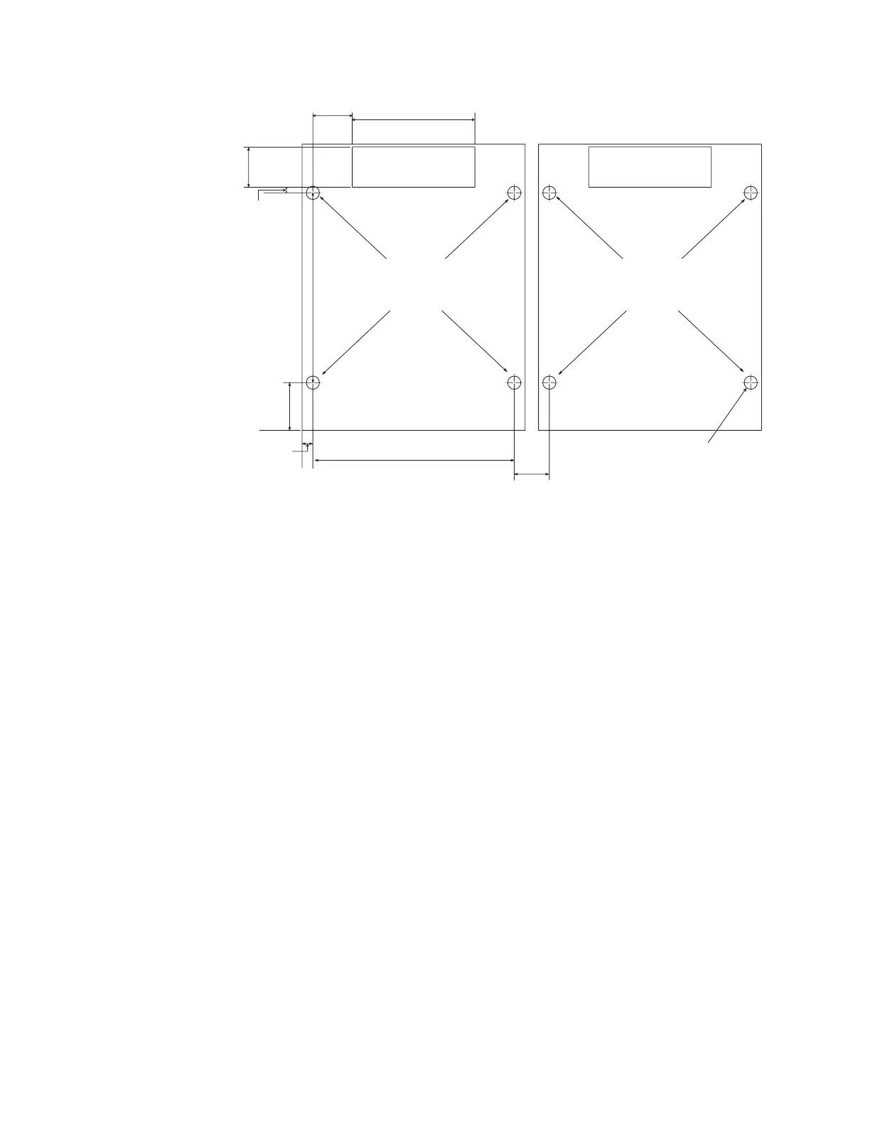
Figure 24. Locations for the cable cutouts and rubber bushing holes in the raised floor and
the eyebolt installation on the concrete floor. The pattern repeats for up to five models.
Dimensions are in millimeters (inches).
156 Introduction and Planning Guide
 Loading...