3. Install the eyebolt fasteners in the concrete floor using the following guidelines:
v Use Figure 24 on page 156 to determine the placement of the eyebolts. The
eyebolts must be installed so that they are directly below the holes that you
cut in the raised floor for the rubber bushings.
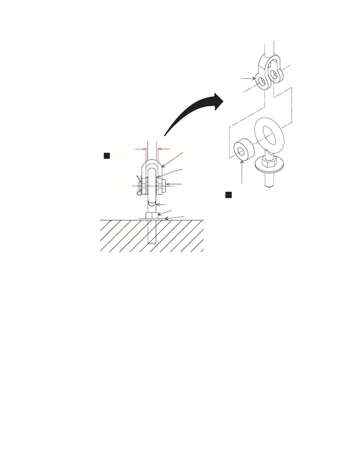
v Ensure that the installed eyebolts do not exceed a height of 101 mm (4 in.)
from the floor to the center of the eye. This maximum height helps to reduce
any bending of the eyebolt shaft.
v Ensure that the installation allows the eyebolts to meet the required pull
force after they are installed (3600 lb pull force for raised floor eyebolts).
v If you use a threaded eyebolt that secures into a threaded insert in the floor,
consider using a jam nut and washer on the shaft of the eyebolt. Talk to your
consultant or structural engineer to determine whether a jam nut is
necessary.
Preparing a nonraised floor for the Earthquake Resistance Kit:
You must prepare a nonraised floor before an Earthquake Resistance Kit can be
installed on any of your storage units racks.
f2c00815
Spacer
Shaft
Eyebolt
Lower
Jaw
Lower
Jaw
Side view of eyebolt
Lower jaw
opening
1.8 (0.71)
Spacer
2.86 (1.13)
1
2
Washer
Jam nut
Figure 25. Eyebolt required dimensions. Dimensions are in millimeters (inches).
Chapter 6. Meeting DS8000 series delivery and installation requirements 157
 Loading...