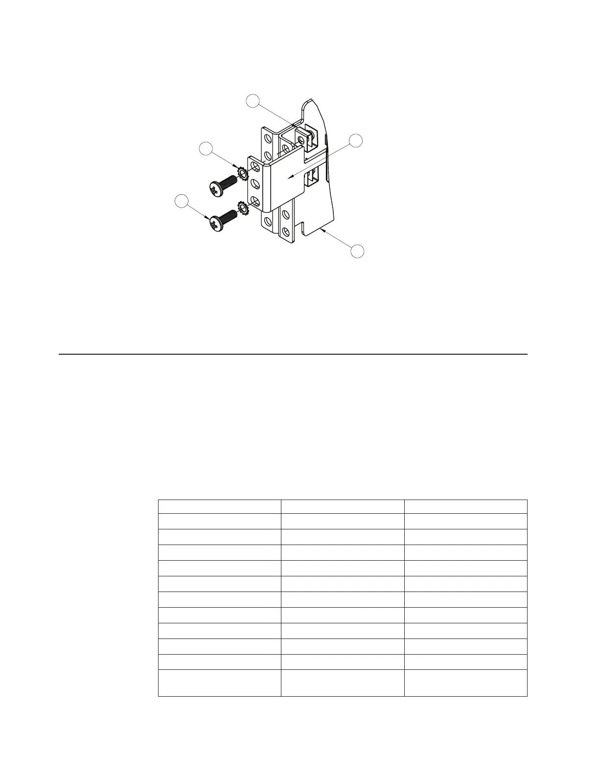
6. Use the M6 washers, screws, and clip nuts to attach the alignment plate. Torque
the screws to approximately 5.7 Nm +/- 0.1 Nm (50 inch-pounds).
8
3
2
4
10
7. Connect all cables.
8. Initialize the switch, see Chapter 4, “Initializing the RackSwitch,” on page 47.
Attention: If this is a switch replacement, make sure the VPD is updated to
avoid losing the licensed electronic entitlement data of the RackSwitch. For
more information, see “Configuring Vital Product Data after a switch
replacement” on page 43.
Installing the RackSwitch in an IBM System x or Power rack
This section provides general information about installing the RackSwitch G8052 in
an IBM System x
®
type 4-post rack, such as the IBM e1350. For information about
mounting the G8052 in other rack types, see the following sections:
v “Installing the RackSwitch in a standard equipment rack” on page 17
v “Installing the RackSwitch in an IBM iDataPlex rack” on page 20
The following table lists the parts included in the IBM System Networking adjustable
19” 4-post rail kit .
Table 12. IBM System Networking adjustable 19” 4-post rail mount kit parts
Item number Description Quantity
1 Label 1
2 M6 locking washers 8
3 M3 screws 4
4 M6 screws 8
5 M6 clip nuts 8
6 M6 cage nuts 8
7 M4 screws 16
8 Filler plate 1
9 Switch front bracket 2
10 Rear mounting bracket 1
11 Rear mounting bracket with
cord exit
1
22 IBM System Networking RackSwitch G8052: Installation Guide
 Loading...