Control enclosure components
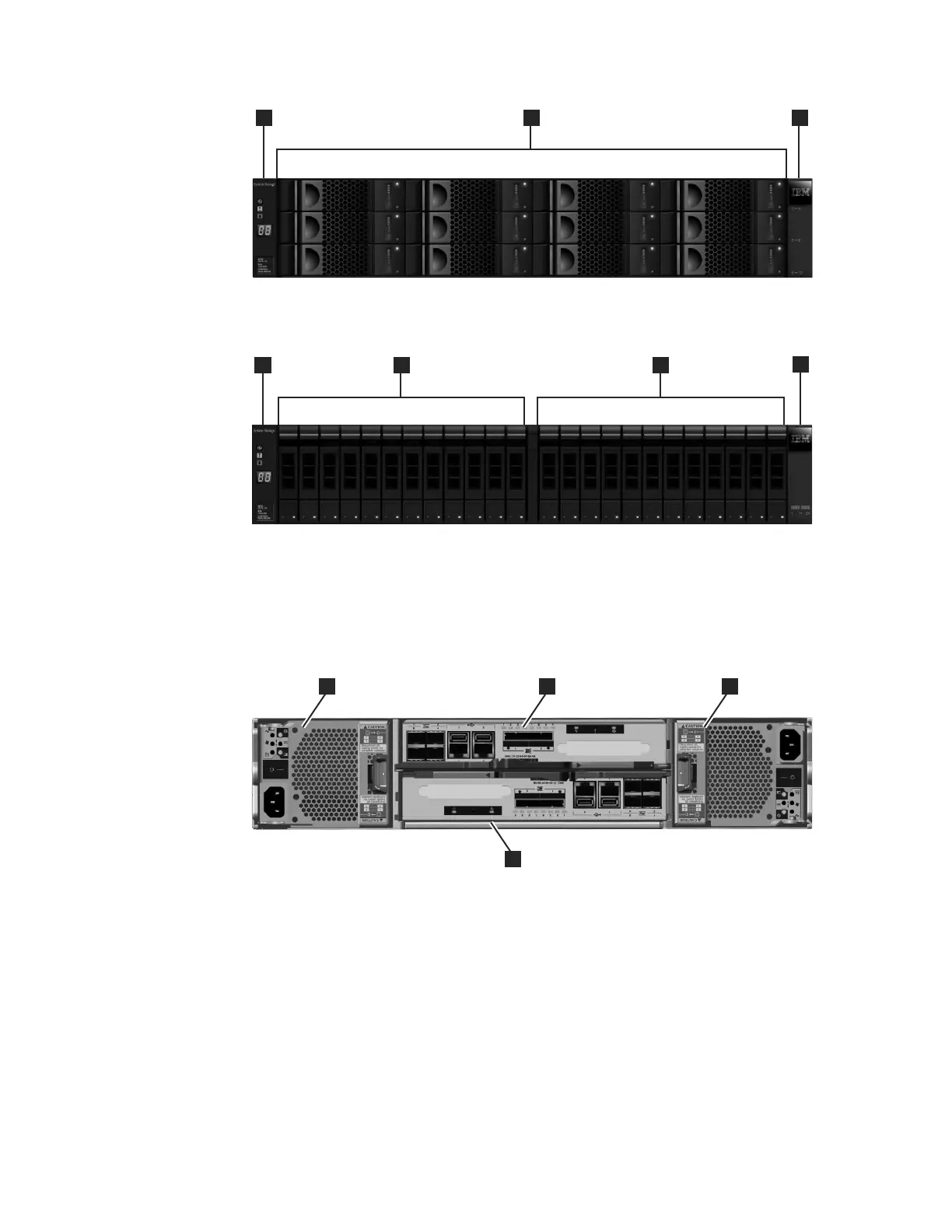
Figure 10 shows the rear view of a control enclosure and identifies the location of
the power supply units and the canisters.
v Power supply units are located on the left and right of the canisters. Each unit
contains a battery. Power supply 1 is located on the left. Power supply 2 is
located on the right. Power supply 1 is inserted top side up, and power
supply 2 is inverted, or top side down.
Important: The power supply units for the control enclosure and expansion
enclosure are not interchangeable.
v Two canisters are housed in the middle of the enclosure. Each canister is known
as a node canister. The upper canister, as shown in Figure 10, is labelled 3, and
the lower canister is labelled 4. Canister 3 is top side up, and canister 4 is
inverted, or top side down.
svc00694
1
2
3
Figure 8. This figure shows 12 drives and two end caps (model 2076-112).
svc00693
1 2 2
3
Figure 9. This figure shows 24 drives and two end caps (model 2076-124).
1
2
3
svc00662
4
Figure 10. Rear view of a model 2076-112 or a model 2076-124 control enclosure
44 IBM Storwize V7000 Unified: Adding Storwize V7000 File Modules to an existing Storwize V7000 system 2073-720
 Loading...


